Wing weight transfer adjustment, Cart weight transfer adjustment – Great Plains NTA2007 Operator Manual User Manual
Page 95
Great Plains Manufacturing, Inc.
Adjustments
91
2012-01-05
166-372M
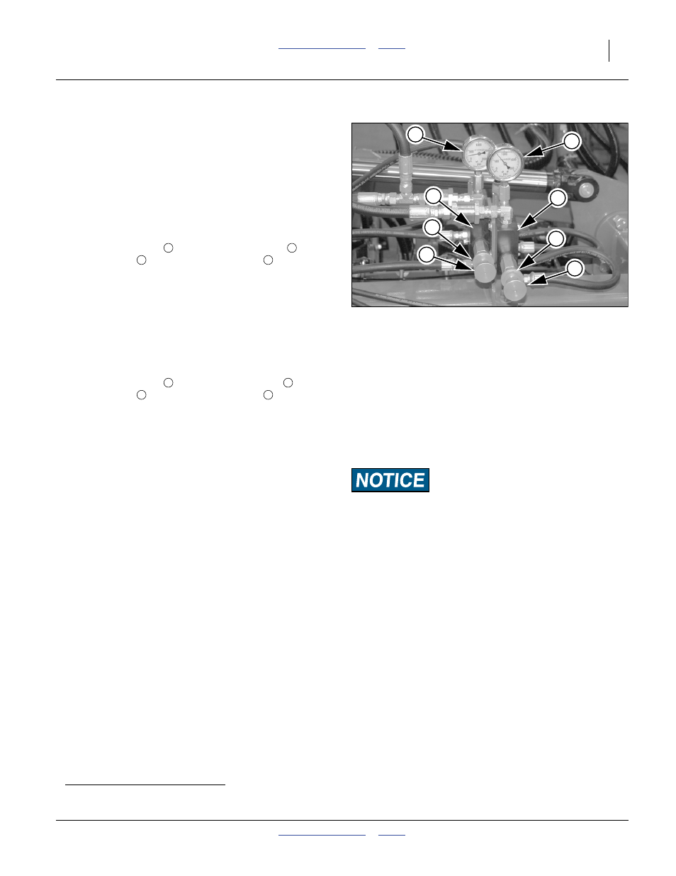
Refer to Figure 69
1.
Hitch drill to suitable tractor (page 26). Hydraulic
power must be available for this adjustment.
2.
Unfold implement (page 36). The wing transfer
adjustment cannot be made with the wings folded.
Set circuit to Neutral.
3.
Lower drill (page 40) in representative field
conditions. Pull forward to put openers in ground.
Wing Weight Transfer Adjustment
4.
Release lock ring
on wing-transfer valve
.
Adjust knob
while observing gauge
.
Increase weight transfer to wings by turning knob
clockwise. Reduce weight transfer to wings by
turning knob counter-clockwise.
Set pressure to at least 250 psi.
Secure setting with lock ring.
Cart Weight Transfer Adjustment
5.
Release lock ring
on cart-transfer valve
.
Adjust knob
while observing gauge
.
Increase weight transfer from cart by turning knob
clockwise. Reduce weight transfer from cart by
turning knob counter-clockwise.
Set pressure to at least 100 psi.
Secure setting with lock ring.
6.
Pull forward in ground. Assess opener penetration,
and coulter (option) penetration. Compare wings
a
to
centre section.
7.
When satisfied with pressure reading, raise
implement while watching pressure gauge. Gauge
reading should drop as you raise implement.
8.
During field operations, monitor coulter and opener
depth of wings and centre section. Adjust weight
transfer as required for consistent depth across drill.
a. Wing operating height is also affected by a levelling eye bolt adjustment (page 133).
Note: To avoid planting problems, do not exceed
1500 psi for wing-transfer, and 1000 psi for cart-
transfer. A relief valve prevents operating the wing-
transfer at over 1500 psi.
Material Rate Risk:
Do not set cart weight transfer higher than necessary.
Values close 1000 psi can lift the rear of an empty cart off the
ground. As a cart nears empty, the main tires can begin to slip,
or stop turning altogether, resulting in irregular seeding rates
or stoppages.
Figure 69
Weight Transfer Valves
31192
1
2
3
4
6
7
5
8
3
1
4
5
6
2
7
8