Implement lift switch adjustment – Great Plains NTA2007 Operator Manual User Manual
Page 121
Great Plains Manufacturing, Inc.
Maintenance and Lubrication
117
2012-01-05
166-372M
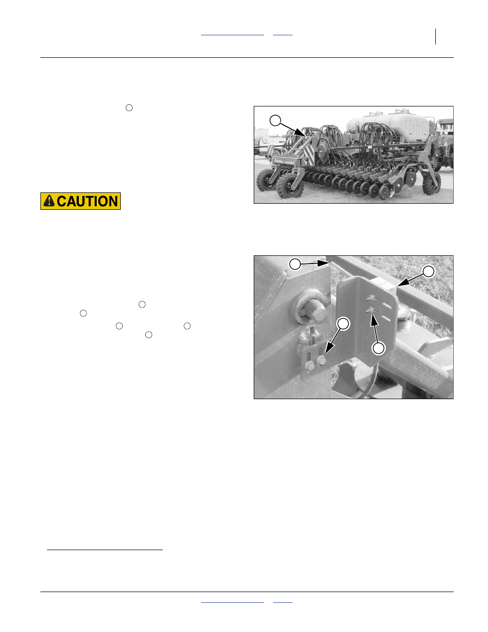
Implement Lift Switch Adjustment
Refer to Figure 95 and Figure 96
An implement lift switch
on the drill turns seed
metering off when the implement is raised, by
commanding
a
a linear motor to retract the ground drive
arm. To adjust the switch activation height, first locate the
lift switch on the implement (centre section, right rear
parallel arms).
If changes have been made to tool bar height (page 32),
or if the switch was removed for any reason, it needs to
be adjusted for activation height.
Pinch / Crush Hazards:
Shut off tractor and remove key while adjusting switch. Do not
place any part of body under implement or near moving parts
while checking adjustments.
Wings must be unfolded to prevent lift lock from
engaging. Lower the openers until at a height where
seeding should start (usually just above ground). Turn off
the tractor and remove the key. Securely support centre
section tool bar at this height with jack stands or blocks.
Loosen switch pivot screws
. Adjust switch angle so
that toggle
is level, or slightly tilted up to the right.
Loosen bracket bolts
and slide switch
up or down
until the flexible switch toggle
is just past the point at
which the switch is activated (flexible switch toggle
deflected up).
Note: The implement lift switch has three wires (black,
red and green). In order for the switch to work
properly, the correct two leads must be connected
to the lift switch extension cable.
The extension cable black lead always connects to
the switch black wire. The extension cable red lead
must connect to the switch green wire.
a. The contact drive also disengages on Master SW Time-out (master switch ON, but ground speed 0 for a period of time greater than
specified in the configuration menus). If the variable Rate Kit option is installed, and the seed monitor is in either of
GRAN SEED CONTROL or GRAN FERT CONTROL, the Master Switch must also be ON for ground drive to engage.
Figure 95
Lift Switch Location
31262
1
1
Figure 96
Lift Switch Adjustment
31263
2
3
4
1
2
3
4
1
3