Air systems overview – Great Plains NTA2007 Operator Manual User Manual
Page 63
Great Plains Manufacturing, Inc.
Operating Instructions
59
2012-01-05
166-372M
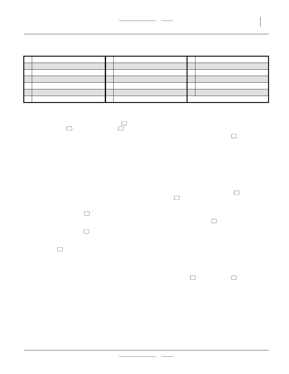
Air Systems Overview
1.
Hydraulic Fan (page 60)
The fan generates the air flow required to deliver
material to the rows. Speed is adjusted via the
tractor circuit. Output is monitored via rpm
,
pressure gauge
and pressure sensor
.
2.
Fan RPM Sensor (page 87)
The seed monitor reports fan rpm based on this
sensor. Although it is accurate for rate, it cannot
detect a fan running in reverse.
3.
Diverter Vane (page 89)
This is present only on dual-hopper drills, and
controls airflow balance between the meters. This
may need adjustment with dissimilar material
metering.
4.
Manifold Pressure Gauge(s) (page 87)
There is one gauge per hopper, mounted for ease of
observation from the tractor cab. These report
whether or not the air system is within recommended
limits. On dual-hopper systems, the gauges assist in
setting the diverter vane
.
5.
Meter Inlet Manifold (page 89)
Fan air is divided (or further divided) into equal flows
for each meter inlet port
.
6.
Hopper (page 52)
Material (seed or fertilizer) flows into the top of the
seed meter
.
7.
Pressure Balance Lines
Each hopper contains an internal pressure-
balancing system to equalize pressure above and at
the base of the material.
8.
Hopper Pressure Sensor
This sensor signals the seed monitor, which can
alarm if the hopper pressure goes out of limits. A
dual hopper drill has two sensors.
9.
Seed Meter
The meter combines material with air flow. It also has
features for rate Range, calibration and clean-out.
10. Flute Shaft (page 168)
Two (and optionally; three or four) sets of flute “stars”
control the flow of seed from the hopper into the air
streams.
11. Flute Shaft RPM Sensor (page 76)
This shaft encoder provides metering rate data,
stoppage alarms, and is used by the optional
Variable Rate Kit to control metering rate.
12. Meter Outlet Ports
Material falls from the meter flutes
into the air
streams flowing from inlet manifold to outlet ports.
Each port is a separate compartment.
13. Single-Shoot Y-Tube
A two-hopper drill may optionally have the output of
both meters combined into a single stream to a
single set of towers. The flows combine at Y-tubes
behind the meters.
14. Primary Seed Hose
Four (single-hopper/shoot) or eight (double-shoot)
hoses deliver seed from the meters
to the
towers
.
15. Distribution Tower
The riser tube and distribution rings have features to
evenly divide the primary hose material flow into
multiple secondary hose
flows. There are four
towers on single-hopper and single-shoot drills, and
eight towers on double-shoot drills.
16. Blockage Sensor
Each tower outlet port has a sensor that detects
material passage and signals the seed monitor. The
primary function of this sensor is to trigger an alarm
on flow stoppage.
17. Secondary Seed Hose
These hoses deliver material from a tower outlet port
to a seed tube
or fertilizer tube
18. Tramline Diverter (Option, page 146)
19. Opener Seed Tube
Seed from hopper I (and hopper II on single-shoot
drills) is delivered in-furrow ahead of the seed firmer.
20. Opener Fertilizer Tube (page 98)
On a dual-hopper double-shoot drill, the material
from hopper II is delivered to this tube above the
seed firmer and furrow.
1 Hydraulic Fan
8 Hopper Pressure Sensor
15 Distribution Tower
2 Fan RPM Sensor
9 Seed Meter
16 Blockage Sensor
3 Diverter Vane
10 Flute Shaft
17 Secondary Seed Hose
4 Manifold Pressure Gauge
11 Flute Shaft RPM Sensor
18 Tramline Diverter
5 Meter Inlet Manifold
12 Meter Outlet Ports
19 Opener Seed Tube
6 Hopper
13 Single-Shoot Y-Tube
20 Opener Fertilizer Tube
7 Pressure Balance Lines
14 Primary Seed Hose
2
5
8
3
5
9
10
9
15
17