Levelling implement, Wing levelling (eye bolts) – Great Plains NTA2007 Operator Manual User Manual
Page 137
Great Plains Manufacturing, Inc.
Maintenance and Lubrication
133
2012-01-05
166-372M
Levelling Implement
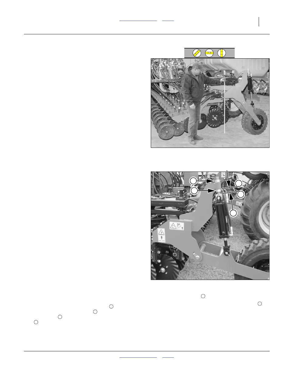
Refer to Figure 123
When fully raised, the opener tool bars of all three
sections should be at the same height. This
measurement is most accurately made on a flat paved
surface.
Implement operating height/level is controlled at several
points:
• Centre frame tool bar height is controlled by spacers
on the lift cylinder rods. See page 86.
• Front-to-back level is automatic. User adjustment of
the lift link is not recommended. In the event of
dismount during maintenance or repair, factory link
length is 2020 mm (79
17
⁄
32
inch) centre-to-centre.
• Wing tip tool bar height is primarily controlled by
gauge wheel cylinders.
• Wing tilt is controlled by wing weight transfer. The
weight transfer adjustment necessary varies with field
conditions. See page 91.
Wing Levelling (Eye Bolts)
Wing tip tool bar height is normally set by the wing lift
cylinders. These are re-phasing cylinders operating as
slaves to the centre section (master) lift cylinders. The
master cylinder lowering limit is set by spacers.
If wing tip tool bar height is not the same as the centre
section tool bar height, make these checks before
considering any adjustment to the eye bolts:
1.
Page 120: Is the lift system charged and bled?
If there is any air in the system, the wing heights may
not track the centre height (or each other).
2.
Page 120: Is the lift system re-phased? If the wing
cylinders are not tracking the centre cylinders,
perform a re-phase.
3.
page 152: Check tire inflation.
4.
Page 91: Is weight transfer properly set for
conditions? If the wing gauge wheels are off the
ground (or nearly so), there may be too little weight
transfer. If the centre section is running high, and the
wing ends are low, there may be too much transfer.
Refer to Figure 124
5.
Check the current eye bolt setting. Prior to any
adjustment, make sure that it was at the factory-
recommended setting. The distance
from the
base of the cylinder lug tube
to the flat top of the
eye bolt lug
is factory-set to:
57 mm (2.25 inch)
To adjust the gauge wheel height:
6.
Unfold the implement on flat ground. Fully raise the
implement.
7.
Loosen the jam nut
.
8.
Set the gauge wheel height with the adjust nut
.
Adjust until opener tool bar height at wing tip is the
same as centre opener tool bar height.
9.
Tighten the jam nut.
Note: If the left and right wing cylinders are not operating
identically, the problem is hydraulic, and not a
mechanical adjustment.
Figure 123
Implement Lateral Level Check
31421
1
Figure 124
Wing Gauge Wheel Eye Bolt
31264
2
3
4
5
1
2
3
1
4
5