Appendix c - option installation, Changing meter flutes – Great Plains NTA2007HD Operator Manual User Manual
Page 167
Great Plains Manufacturing, Inc.
163
04/04/2011
166-283M
Appendix C - Option Installation
Changing Meter Flutes
To order high rate flute shafts, see “High Rate Flute
Sets” on page 141. To install a set of these shafts (or re-
install the standard shafts), start with the front meter, as
the task is a bit easier there. Save all parts for re-use.
Hopper must be empty for this procedure. see “Unload-
ing Materials” on page 108.
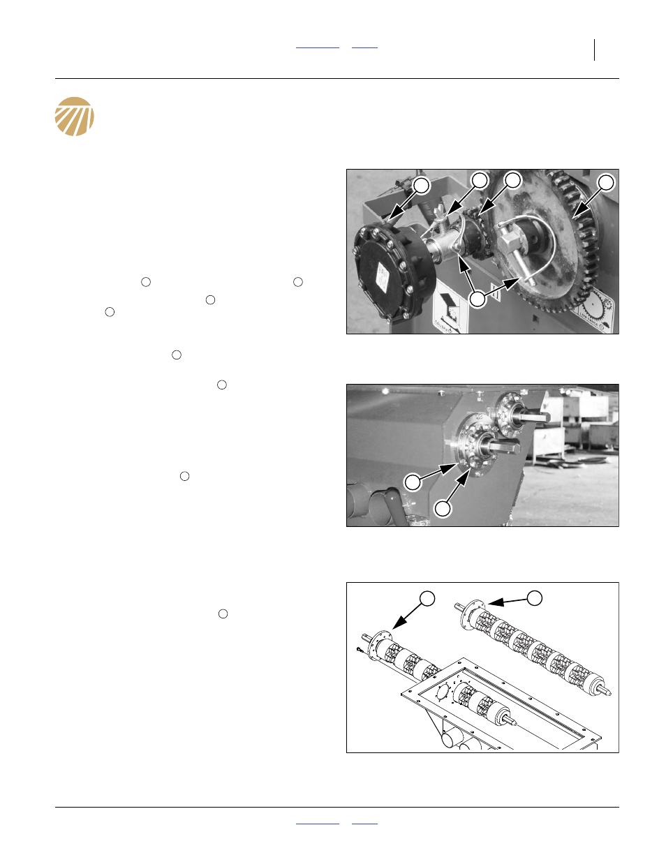
Refer to Figure 147
1.
On the left end of the meter box, release the anti-
rotation strap
, and loosen the thumbscrew
2.
Remove and save the pins
from the final range
gears
, and then remove and save the gears.
Refer to Figure 148
3.
Remove and save the outer ring of six (6) self-tap-
ping hex head bolts
, that secure the outer flange
to the meter box.
Note: Do not remove the six bolts
that secure the bear-
ing flangette to the outer flange. The shaft to be in-
stalled includes its own flange.
Refer to Figure 149 (Shown with meter box off and various
components removed for clarity. It is not necessary to dis-
mount or further disassemble meters to swap flute shafts).
4.
From the left end of the meter box, carefully withdraw
the current flute shaft
. It is likely that the flange
has a bead of silicone gasket. You may need to care-
fully pry the flange loose from the box.
5.
Store the old shaft in the carton in which the new
shaft was supplied. Mark the carton with the number
of active hoses (towers) and the number of stars
(factory standard is 2). This will reduce the risk of
mistaking the carton/contents in the future.
6.
Apply a bead of silicone sealant to the inside face of
the outer flange, just inside the bolt hole pattern.
7.
Carefully insert the new shaft
in the meter box.
8.
When the flange on the left end is fully seated
against the box, secure it with the 6 saved bolts. Give
the shaft a few turns.
9.
Re-mount the gears. Refer to the Seed Rate manual
for the gear assignments for the agitator and flute
shafts. Note the pin hole orientation on the shaft and
on the gears. The gears can only be pinned in 2 of
the 6 possible ways they can be placed on the
shafts.
Null4:
Figure 147
Remove Gears
31373
4
3
4
1
2
2
3
4
5
Null4:
Figure 148
Remove Flange Bolts
26338
6
5
6
7
Null4:
Figure 149
Exchange Flute Shafts
26335
7
6
6