10 – installation of cylinder, Fig. 1 fig. 2, Fig. 1 fig. 3 fig. 2 – SARGENT Profile Series v.G1.5 Mortise Locks User Manual
Page 14
Profile Series v.G1.5 Mortise Dorm Lock
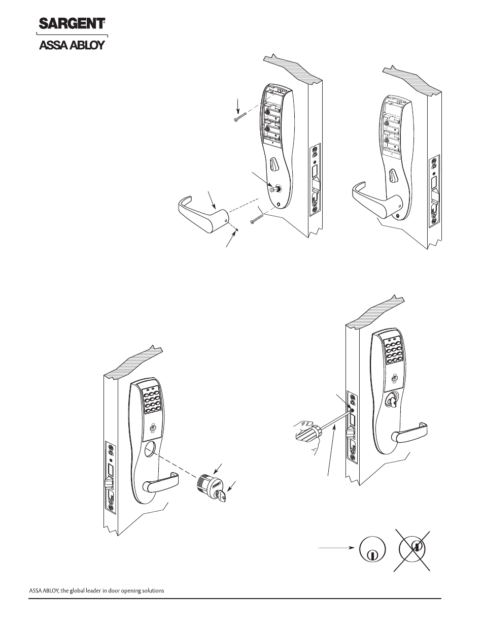
6.9 – Attaching Inside Escutcheon & Lever
Inside of
door
•
Set
screw
Inside lever
Outside of door
Type 43 Mortise
cylinder ONLY
Key
SARGENT
S
A
R
G
E
N
T
Note: Key and
cylinder must be
rotated as shown
Correct
Incorrect
Phillips
screwdriver
Set screw
Spindle
Flat head
screw
1. Rotate and hold the thumb turn to the vertical
position. While locating inside escutcheon against
the door, align thumb turn tail with slot in lockbody.
2. Though bolt inside escutcheons to outside
escutcheon with (2) # 8-32 x 1-7/8" flat head
screws (Ref. Fig. 1).
3. Slide lever handle onto spindle until fully seated
(as shown in Fig. 2). Be sure handle is horizontal
and facing to the rear of the door.
4. Tighten the set screw securely with 1/8"
hex wrench.
Fig. 1
Fig. 2
6.10 – Installation of Cylinder
1. Align cylinder (as shown in Fig. 1)
2. Screw cylinder into lockbody unit (Ref. Fig. 3 for cylinder orientation)
3. Tighten the set screw to prevent unscrewing of the cylinder (Ref. Fig. 2).
4. Turn the keyway in the cylinder to make certain that the locking mechanism
functions correctly.
Inside of
door
•
Set
screw
Inside lever
Outside of door
Type 43 Mortise
cylinder ONLY
Key
SARGENT
S
A
R
G
E
N
T
Note: Key and
cylinder must be
rotated as shown
C
Phillips
screwdriver
Set screw
Spindle
Fig. 1
Fig. 3
Fig. 2
Inside of
door
•
Set
screw
Inside lever
Outside of door
Type 43 Mortise
cylinder ONLY
Key
SARGENT
S
A
R
G
E
N
T
Note: Key and
cylinder must be
rotated as shown
Correct
Incorrect
Phillips
screwdriver
Set screw
Spindle
12
© SARGENT Manufacturing Company 2006, 2007
For installation assistance, contact SARGENT at 800-810-WIRE (9473)