Profile series v.g1.5 mortise dorm lock, Ca b – SARGENT Profile Series v.G1.5 Mortise Locks User Manual
Page 13
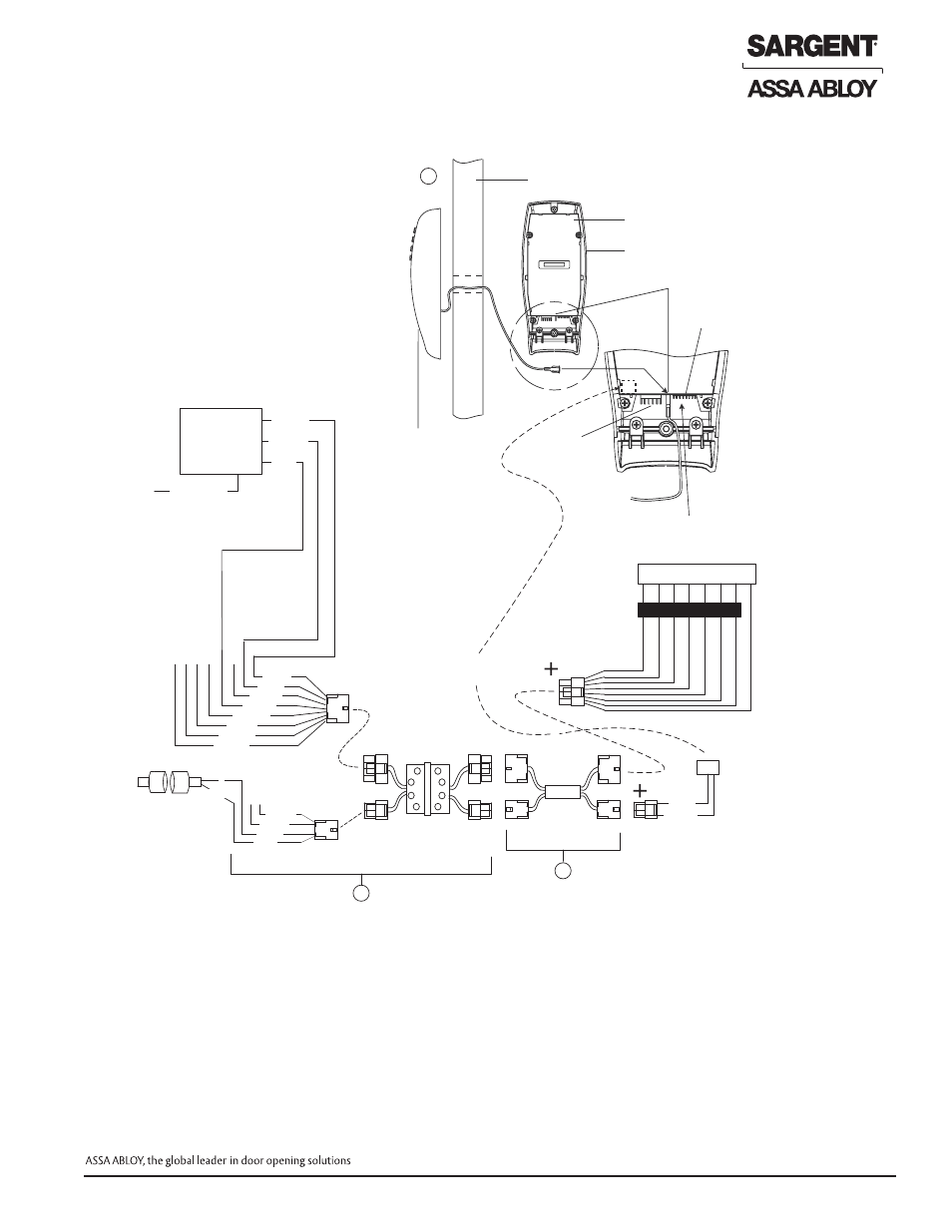
Fig. 3
Remote Power,
Remote & Forced/
Propped Door
ElectroLynx Wiring System
91-Prefix
(52-3010)
Remote Power &
Unlocking Harness
Ground Tab E3
Inside Escutcheon
Power/Remote
Unlock Connector TB2
6 AA batteries MUST be removed from
controller if 3267 Power Supply is used
Door
Motor
Connector
TB1
Outside Escutcheon
C
A
B
3, Pink
4, Tan
1
2
3
Tan, 4
Pink, 3
Gray, 2
Violet, 1
C
*NC
Door Status Switch
*Wire for switch contact
closure when door
is opened
**QC12 Electric Hinge
with 8 & 4-pin connectors,
12 wires and pigtail harness
ElectroLynx Door Harness
with 8 & 4-pin connectors.
Harness location is dependent
on door type.
DM- prefix
(52-3409)
Forced/Propped
Door Harness
Re
d
Bl
ac
k
+9
(-)
(E
G
ND
)
G
re
en
O
ra
ng
e
W
hi
te
RE
X
RE
X
1
2 3
7
6
5
4
8
Bl
ue
Br
ow
n
Ye
llo
w
Da
ta
O
ut
Da
ta
In
RT
S
Blue, 6
White, 3
Red, 2
Black, 1
Brown, 7
Orange, 5
Green, 4
Yellow, 8
3267
9VDC
Power Supply
-
9 VDC
+9 VDC
EGND
Note: Refer to 3267 Power Supply
Instruction A7477
120VAC L/N/G
Forced/Propped Door
Connector J4
Installation
1. ElectroLynx System Wiring Instructions (refer to Fig. 1 and 3)
a. Look for the mating part on ASSA ABLOY doors & frames. Then, plug in all connectors as shown in
Fig. 3 during product installation
b. Hard wire forced/propped door and/or hard power, as shown
2. Non-ElectroLynx System Wiring Instructions (refer to Fig. 1 and 3)
a.
+
Cut the 8-pin and/or 4-pin connector(s) as marked, and hard wire to door harness
b. Hard wire door harness to power transfer device
c. Hard wire door status switch and/or 3267 Power Supply to power transfer (as shown)
Hard Power (91- prefix) with Forced/Propped Door (DM-)
**NOTE: For Hard Power only - QC8 required instead of QC12
Profile Series v.G1.5 Mortise Dorm Lock
11
© SARGENT Manufacturing Company 2006, 2007
For installation assistance, contact SARGENT at 800-810-WIRE (9473)