Profile series v.g1.5 mortise dorm lock – SARGENT Profile Series v.G1.5 Mortise Locks User Manual
Page 12
3, Pink
4, Tan
1
2
3
Green, 4
White, 3
Black, 2
Red, 1
C
*NC
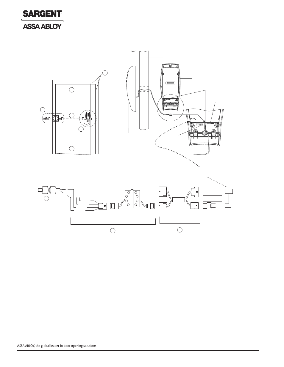
Door Status Switch
*Wire for switch contact
closure when door
is opened. Typical
locations shown in Fig. 1
QC4A Electric Hinge
with 4-pin connectors
and pigtail harness
ElectroLynx Door Harness
with 8 & 4-pin connectors.
Harness location is dependent on
door type.
DM- prefix
(52-3409)
Forced/Propped
Door Harness
Fig. 1
Fig. 2
Forced/Propped Door Option
ElectroLynx Wiring System
4-pin
connector
Forced/Propped Door
Connector J4
Ground Tab E3
Inside Escutcheon
Power/Remote
Unlock Connector TB2
Door
Motor
Connector
TB1
Outside Escutcheon
B
A
B
B
C
D
B
A
D
C
Installation
1. ElectroLynx System Wiring Instructions (refer to Fig. 1 and 2)
a. Look for the mating part on ASSA ABLOY doors & frames. Then, plug in all connectors as shown in Fig. 2
during product installation
b. Hard wire door status switch as shown
2. Non-ElectroLynx System Wiring Instructions (refer to Fig. 1 and 2)
a. Cut the 4-pin connector off the Forced/Propped harness and hard wire to non-ElectroLynx two conductor
door harness
b. Hard wire door harness to power transfer device
c. Hard wire door status switch to power transfer device
6.8.D – Forced/Propped Door Option (DM-)
Profile Series v.G1.5 Mortise Dorm Lock
10
© SARGENT Manufacturing Company 2006, 2007
For installation assistance, contact SARGENT at 800-810-WIRE (9473)