2 hook up to express key control box, Hook up to express key control box – Unitec Wash Select II POS Installation Manual User Manual
Page 31
W A S H
S E L E C T
I I
Document Number:
WS21001
25
Document Title:
Wash Select II POS Installation Manual
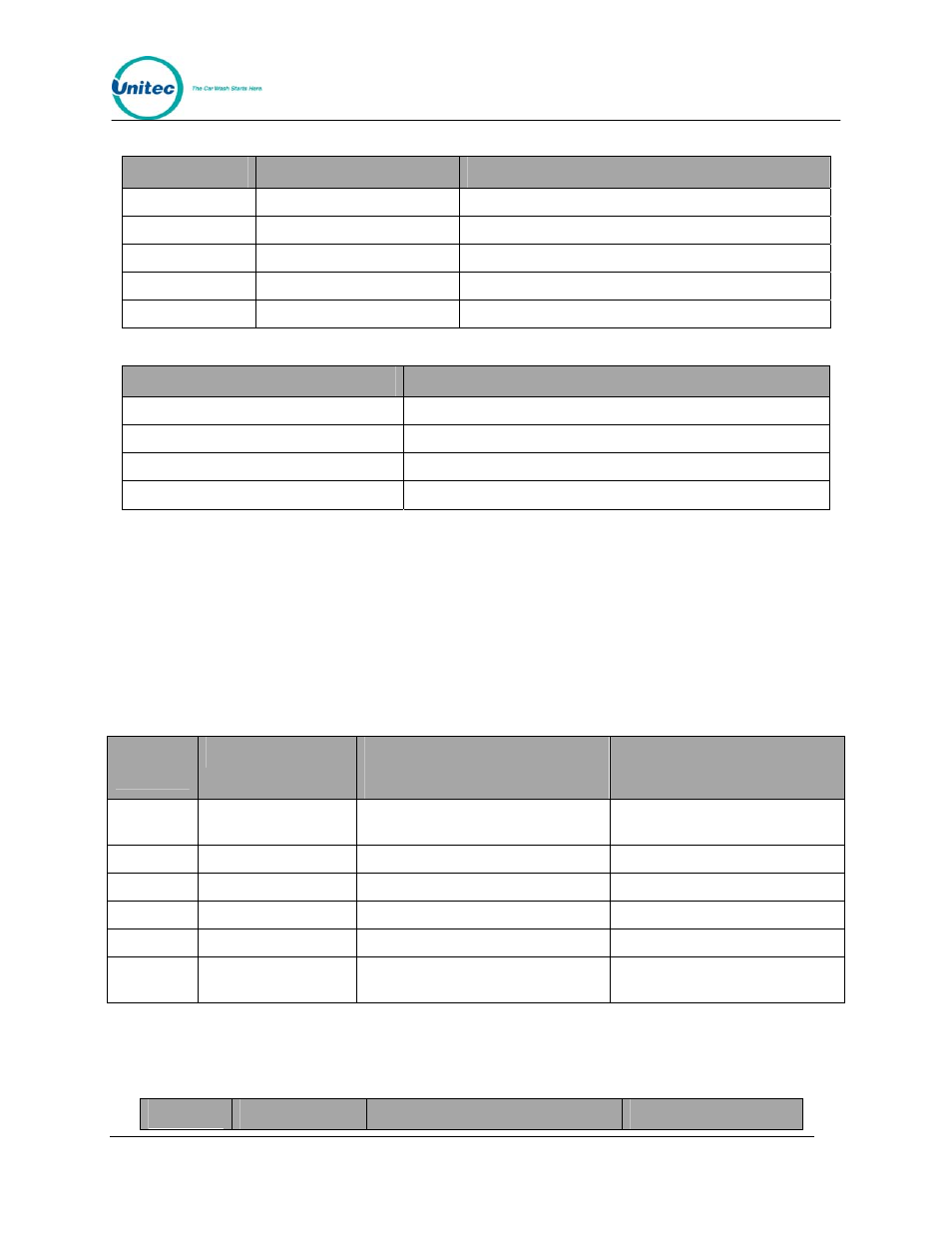
Table 6. J 2 of Unitec Wash Card interface board
Pin Number
Signal Name
Connect to
1
Output 1 N.O.
Washcard TB-A pin 10 (Input 5)
2
Output 2 N.O.
Washcard TB-A pin 12 (Input 6)
3
Output 3 N.O.
Washcard TB-A pin 14 (Input 7)
4
Output 4 N.O
Washcard TB-A pin 16 (Input 8)
5
Output Common
Washcard TB-A pin 11 (Common 5+6)
Table 7. Washcard input assignments
Input
Corresponding Wash Select II wash & display
Washcard TB-A pin 10 (Input 5)
Wash 1 (Display at bottom) typically least expensive wash
Washcard TB-A pin 12 (Input 6)
Wash 2 (Display 2
nd
from bottom)
Washcard TB-A pin 14 (Input 7)
Wash 3 (Display 2
nd
from top)
Washcard TB-A pin 16 (Input 8)
Wash 4 (Display at top) typically the most expensive wash
4.8.2 Hook Up to Express Key Control Box
Remove connector J1 from the Ext Fleet card on the lower left of the I/O board and make the
following connections.
(The Express Key control box has recently been changed. It is important that you know which
version your unit has when making the connections. The old version is a large white box. The
new version is a small green circuit board.
Table 8. J1 of Unitec Wash Card interface board
Pin
Number
Signal Name
Connect to
(Old Version)
Connect to
(New Version)
1
Input 1 A
Express key JP 3 Relay In (purple)
Express key JP 3 Relay In
(spade plug)
2
Input 1 B
Pin 5 of J1 (this connector)
Pin 5 of J1 (this connector)
3 Input
2
A
4 Input
2
B
5
10-16VDC+ Isolated
Pin 2 of J1 (this connector)
Pin 2 of J1 (this connector)
6
10-16VDC-
Isolated Express key JP 3 Relay Out
(brown/white)
Express key JP 3 Relay Out
(spade plug)
Remove connector J2 from the Ext Fleet card on the lower left of the I/O board and make the
following connections:
Table 9. J 2 of Unitec Wash Card interface board
Pin
Signal Name
Connect to
Connect to: