Fabricator 211i installation/setup, 18 wire reel brake – Tweco 211i Fabricator User Manual
Page 54
FABRICATOR 211i
INSTALLATION/SETUP
INSTALLATION/SETUP
3-22
Manual 0-5157
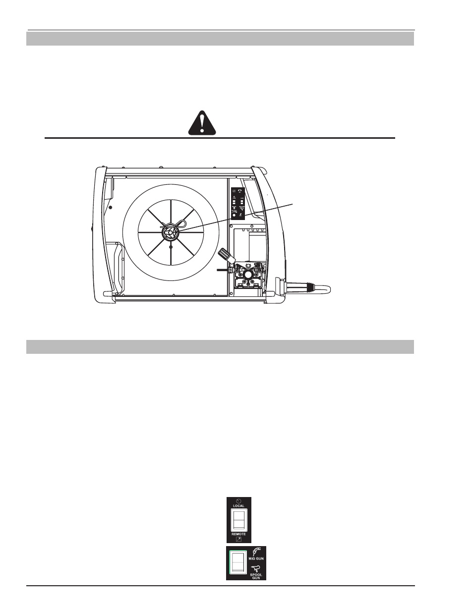
3.18 Wire Reel Brake
The wire reel hub incorporates a friction brake which is adjusted during manufacture for optimum braking.
If it is considered necessary, adjustment can be made by turning the Thumb Screw inside the open end of the hub
clockwise to tighten the brake. Correct adjustment will result in the wire reel circumference continuing no further
than 1/8"-3/16" (3-5mm) after release of the trigger. The electrode wire should be slack without becoming dislodged
from wire spool.
CAUTION
Overtension of brake will cause rapid wear of mechanical WIREFEED parts, overheating of electrical com-
ponentry and possibly an increased incidence of electrode wire Burnback into contact tip.
Spool Hub Tension
Thumb Screw
Art # A-10429
Figure 3-18: Wire Reel Brake
3.19 Setup For MIG (GMAW) Welding With Gas Shielded MIG Wire
A. Select MIG mode with the process selection control. (Refer to Section 3.10.13 for further information)
B. Connect the MIG polarity lead to the positive welding terminal (+). If in doubt, consult the electrode wire manufac-
turer. Welding current flows from the Power Source via heavy duty bayonet type terminals. It is essential, however,
that the male plug is inserted and turned securely to achieve a sound electrical connection.
C. Fit the MIG gun to the power source. (Refer to section 3.11 Attaching the TWECO Fusion 220A MIG gun).
D. Connect the work lead to the negative welding terminal (-). If in doubt, consult the electrode wire manufacturer.
Welding current flows from the Power Source via heavy duty bayonet type terminals. It is essential, however, that
the male plug is inserted and turned securely to achieve a sound electrical connection.
E. Fit the welding grade shielding gas regulator/flowmeter to the shielding gas cylinder (refer to Section 3.06) then
connect the shielding gas hose from the rear of the power source to the regulator/flowmeter outlet.
F. Refer to the Weld Guide located on the inside of the wirefeed compartment door for further information.
G. Switch the LOCAL/REMOTE switch inside the
wire feed compartment to LOCAL to use the
Power Sources Wirespeed and Voltage controls.
H. Switch the MIG GUN/SPOOL GUN switch inside
the wire feed compartment to MIG GUN.