Gcm 2010 gas control module: controls & indicators, Mode selection switch mode, Gcm 2010 – Tweco 400 Ultra-Cut(October 2014) User Manual
Page 71
ULTRA-CUT 100 XT/200 XT/300 XT/400 XT
Manual 0-5264
OPERATION
4-7
GCM 2010 Gas Control Module: Controls & Indicators
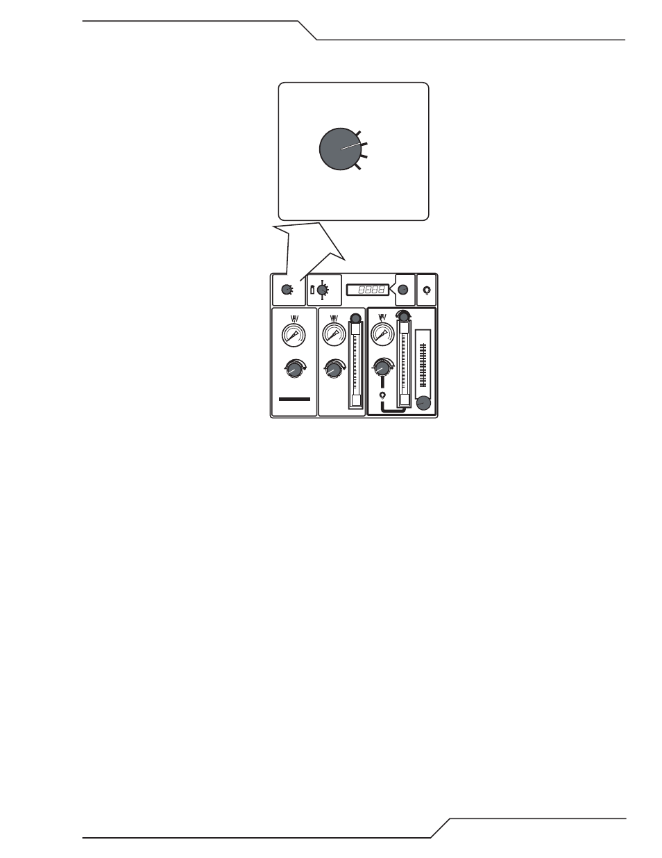
1. MODE Selection Switch
MODE
RUN
SET PREFLOW
SET PLASMA
& SHIELD
TEST
PREFLOW
H
2
O
MIST
PLASMA
SHIELD
PRESSURE
PLASMA
POWER SUPPLY
GAS
FLOW
High Precision
Plasma Cutting System
ENABLE
DISABLE
GAS
MODE
RUN
SET PREFLOW
SET PLASMA
& SHIELD
TEST
O2 - AIR
O2 - O2
H35 -N
2
F5 - N
2
AIR - AIR
N
2 -
H
2
O
N
2 -
N
2
Art # A-04765_AB
9
9
GCM
2010
• Normally in the RUN position during torch operation.
• In the SET PREFLOW position, Preflow or Piloting gas (Air or N
2
) flows to the torch allowing the operator to
adjust pressure. Gas automatically shuts off after 2 minutes if left in the SET PREFLOW position.
• In the SET PLASMA & SHIELD position, selected cutting gases, Plasma & Shield, flow to the torch to allow
operator to set the pressure (regulator & gauge) and flow (knob at top of flowmeter). Gases automatically
shut off after 2 minutes if left in the SET PLASMA & SHIELD position. GCM 2010 gas control revision AG or
later includes inlet pressure sensors. In SET PLASMA & SHIELD position the LCD display shows alternately
the plasma an shield inlet pressure. If either gas pressure is outside the acceptable range, the display shows
“PSI low (or high), the actual pressure and the limit it is below (or above).
• In the TEST position , selected cutting gasses, Plasma & Shield, also flow to the torch. The Plasma outlet pres-
sure (pressure going to the torch), is displayed.
• For GCM 2010 gas control revision AG or later the Mode Selection Switch includes a hidden function used at
initial setup to configure the gas control for the gas lead length. See Sequence of Operation, initial setup.