Tweco 400 Ultra-Cut(October 2014) User Manual
Page 45
ULTRA-CUT 100 XT/200 XT/300 XT/400 XT
Manual 0-5264
INSTALLATION
3-19
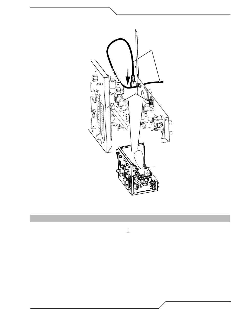
3. Insert the fiber-optic cable connector into the receptacle on the vertically-mounted circuit board as shown.
Cable must snap into place.
Circuit Board
Fiber Optic Cable
Art # A-04773
4. Tighten the through-hole protector for the fiber-optic cable using hand tools.
5. Reinstall the Cover Panel making sure the ground wire is attached.
3.18 Gas Control Module: Control, Input, and Output Connections
1. Make all other connections to the rear of the Module. The connections are labeled. The Module must be
grounded; the grounding terminal is marked Use #10 AWG (European 6 mm
2
) (or thicker) wire for
grounding. Keep the ground wire as short as possible.
2. Position the Module on a flat, horizontal, mounting surface.
3. Ensure that the Flowmeters are plumb.
4. Secure the Module to the mounting surface.
5. Connect all gas / water inputs to the rear panel of the module.
6. Connect the appropriate control cables to terminals marked ‘TVA’ (torch valve assembly) and ‘power sup-
ply’.