21 torch valve installation, Torch valve installation -30 – Tweco 400 Ultra-Cut(October 2014) User Manual
Page 56
ULTRA-CUT 100 XT/200 XT/300 XT/400 XT
3-30
INSTALLATION
Manual 0-5264
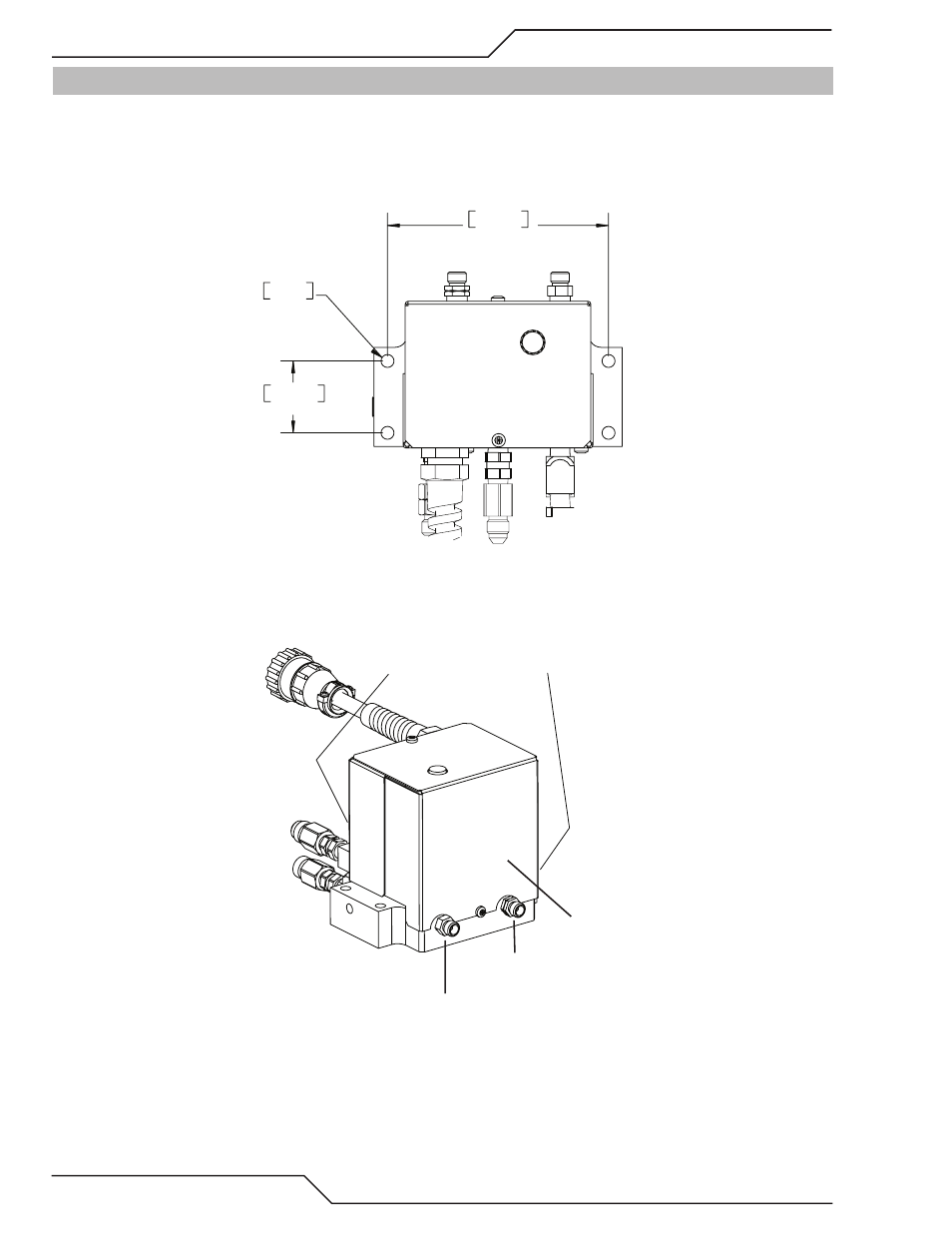
3.21 Torch Valve Installation
General Information
This assembly mounts as close as possible to the torch head. It accepts preflow, plasma, and shield gases from the
Gas Control Module and supplies these gases to the Torch.
Mounting
1.450”
36.83 mm
4.450”
113.03 mm
.261” Dia.
6.63 mm
Art # A-07648
1. Mount the Valve Kit as close as possible to the Torch. The valve kit can be mounted in any convenient posi-
tion, provided the outlet side (with two fittings) is closer to the torch than the inlet side (with three fittings and
a control cable connector).
2. Connect the Valve Kit outlets to the torch leads as shown. (XTL shown)
Art # A-07645
Do not remove brass plugs
Front and side
Right-hand Thread:
To Torch Shield Gas fitting
Left-hand Thread:
To Torch Plasma Gas fitting
Outlet Side