15 height control connections, 16 gas control module installation, Height control connections -16 – Tweco 400 Ultra-Cut(October 2014) User Manual
Page 42: Gas control module installation -16
ULTRA-CUT 100 XT/200 XT/300 XT/400 XT
3-16
INSTALLATION
Manual 0-5264
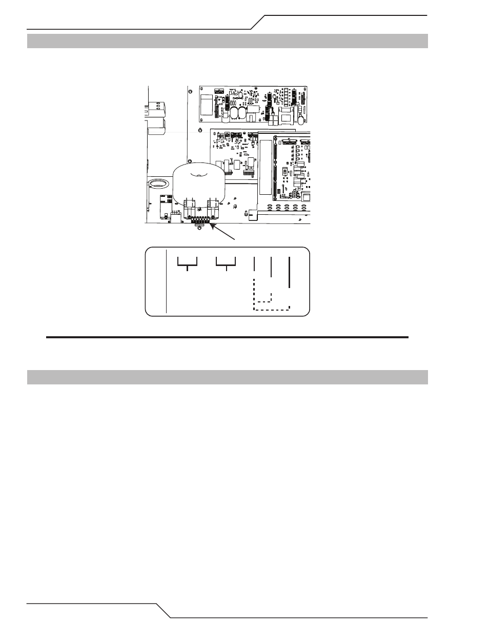
3.15 Height Control Connections
The terminal strip provides connections to negative Arc Volts (Torch or electrode), Tip Volts (Pilot) and Work.
These are for a height control that requires connection to the full non-divided arc voltage. Also available on the
terminal strip are 120VAC and 24 VAC. The allowable current draw is 100ma @ 120VAC and 1Amp @ 24 VAC.
Art # A-11900
24 VAC
@ 1A
TB4
1
2
3
4
5
6
7
120 VAC
@ 100 ma.
Work
Tip Volts
(Pilot)
Arc Volts
(Torch)
Art # A-11954
NOTE
There are holes added in the rear panel for customer wiring. This, rather than the one in the CCM will be
the preferred place for customer added wiring (and strain relief) for connections to height controls, etc..
3.16 Gas Control Module Installation
The Gas Control Module must be installed in a suitable location where it is easily accessible to the system operator.
The unit must be mounted to a flat horizontal surface. If the Module is mounted to a gantry or to any other support
subject to vibration or motion, the installer must fasten the module to the support securely.
The Module should be located as far away as possible from the Arc Starter due to electromagnetic interference. It
is acceptable to locate the control cable in the same track as the cables from the Arc Starter.
The Module includes feet which lift the bottom panel off the mounting surface. There are ventilation holes on the
bottom panel; the space between the bottom panel and the mounting surface must remain open for ventilating air
to enter the module. Louvers on the back panel of the module must also remain unblocked, for the free passage
of ventilating air.