11 connect coolant leads, Connect coolant leads -10 – Tweco 400 Ultra-Cut(October 2014) User Manual
Page 36
ULTRA-CUT 100 XT/200 XT/300 XT/400 XT
3-10
INSTALLATION
Manual 0-5264
5. Increasing the ground rod length beyond 20 - 30 ft (6.1 – 9.1 m) does not generally increase the effectiveness
of the ground rod. A larger diameter rod which has more surface area may help. Sometimes keeping the soil
around the ground rod moist by continuously running a small amount of water into it will work. Adding salt
to the soil by soaking it in salt water may also reduce its resistance. You may also try a chemical ground rod
devise. When these methods are used, periodic checking of the ground resistance is required to make sure the
ground is still good.
E. Routing Of Torch Leads
1. To minimize RF interference, position torch leads as far as possible from any CNC components, drive motors,
control cables, or primary power lines. If cables have to pass over torch leads, do so at an angle. Do not run the
plasma control or other control cables in parallel with the torch leads in power tracts.
2. Keep torch leads clean. Dirt and metal particles bleed off energy, which causes difficult starting and increased
chance of RF interference.
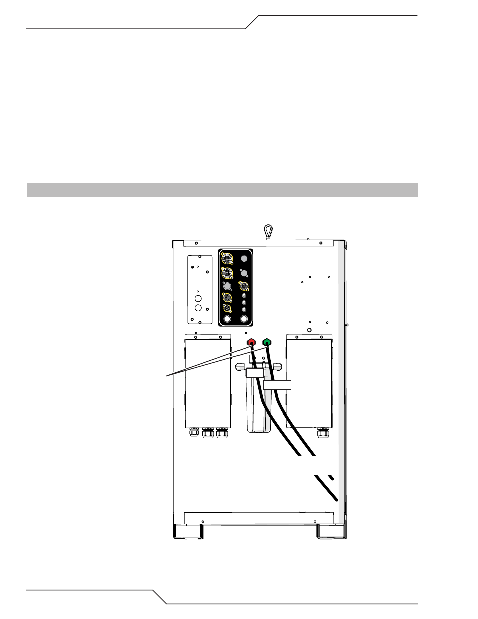
3.11 Connect Coolant Leads
1. Connect the color-coded coolant hoses to the coolant connections on the power supply rear panel. The sup-
ply line (out) is flagged green, the return line (in) is flagged red.
COOLANT
RETURN SUPPLY
Coolant Connections
RED
GREEN
To RAS 1000 Arc Starter or
HE-400 Heat Exchanger if used
Art # A-11534_AB
USER INPUT
HEIGHT CONTROL
F1 - 8A SB 230 VAC
F2 - 8A SB 230 VAC
CB4 - 5A 120 VAC
CB3 - 5A 24 VAC
CB2 - 5A 120 VAC
J55 - GCM
J15 - CNC
J59 - RAS
J70 - HE
J54 - TSC /COMM