Tweco 400 Ultra-Cut(October 2014) User Manual
Page 170
ULTRA-CUT 100 XT/200 XT/300 XT/400 XT
A-64
APPENDIX
Manual 0-5264
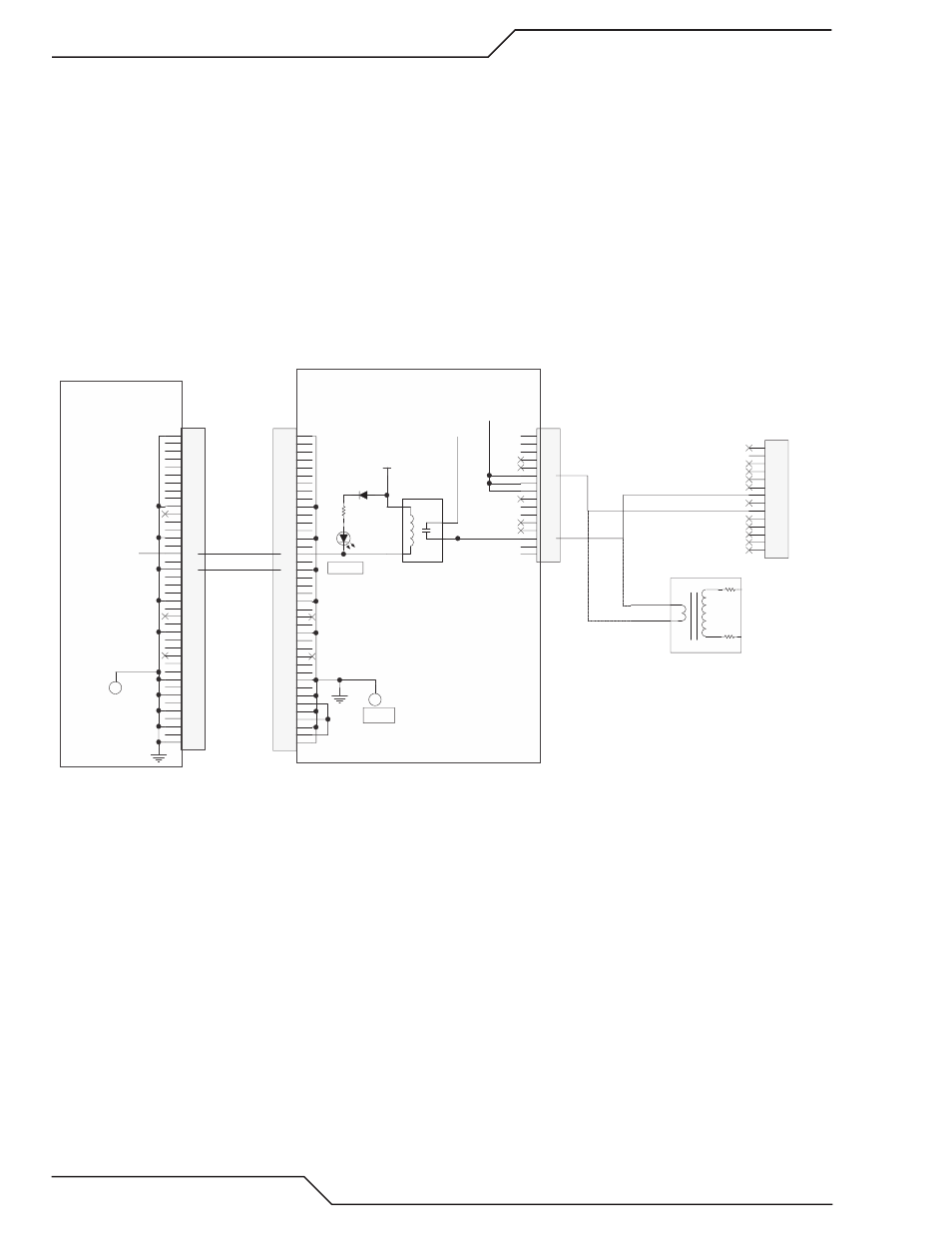
Reasons why RAS Control relay would not close:
6. Pilot current flowing. There actually is pilot current flowing somewhere. Unlikely as it would normally set
the 20� fault but we have to rule it out.
a. Disconnect J41 on the Pilot board, if HF still doesn’t fire and the Relay board Pilot LED, D11, is still
on, it’s due to a fault in the detection circuits.
7. Faulty detection circuit. There isn’t any pilot current but a fault in the circuits measuring pilot current is
indicating there is current.
a. Measure between pins � (-) and 9 (+) on the Pilot ribbon cable from Relay board J3 to Pilot board J42. If
there is no pilot current it should be zero. Anything else indicates the Pilot board current sensor is faulty
causing the Relay board D11 to be on. Replace the Pilot board assembly.
b. If the Pilot current signal on the pilot ribbon cable was zero, measure between pins 23 (-) and 25 (+) on
the 40 pin ribbon cable between the Relay board and the CCM. This would also normally be zero if there
is no pilot current. Anything else would indicate the Relay board is faulty.
Art # 12307
1
2
3
4
5
6
7
8
9
10
11
12
13
14
15
16
17
18
19
20
21
22
23
24
25
26
27
28
29
30
31
32
33
34
35
36
37
38
39
40
J23
TO RELAY BOARD
1
2
3
4
5
6
7
8
9
10
11
12
13
14
15
16
17
18
19
20
21
22
23
24
25
26
27
28
29
30
31
32
33
34
35
36
37
38
39
40
J4
From I/O PCB
24VDC_SW
D21
GREEN
D23
RF ON
1
5
3
4
K2
RAS CONTROL
120
VA
C
120 VAC to RAS
1
2
3
4
5
6
7
8
9
10
11
12
13
14
15
16
J8
120
VA
C
R
ET
120 VAC_1
From J9-1
120 VAC_RET
From J9-7
CCM I/O Board
Relay & Interface Board
1
2
3
4
5
6
7
8
9
10
11
12
13
14
J59 - RAS
(98)
(99)
T2
120 / 6000 VAC
(98)
(99)
6.5K 1W
6.5K 1W
AC200XT only
(Rear Panel)
TP1
GND
TP1
GND
/ RAS ON
�. If “ /RAS ON” signal is low on pin 16 of the 40 pin ribbon cable, relative to TP1 on the CCM I/O board,
during the ignition time then we need to determine if the Relay board is defective. If /RAS ON signal is
not low the CCM or the 40 pin ribbon cable may be defective.
a. If the Relay board RF ON LED, D23, is not on while the /RAS ON signal is low, then the Relay board is
defective.
b. Is D23 is on, measure for 120 VAC on J�-3 to J�-11. If not present the Relay board is defective.
c. If 120 VAC is present at J� during the ignition time go back and perform steps 2-4.