Testing the control, Test, Range access level description item field – tekmar 369 Zone Control Installation User Manual
Page 27
Copyright © D 369 -10/00
27 of 32
369 RTU Misc (Miscellaneous) Menu (1 of 1)
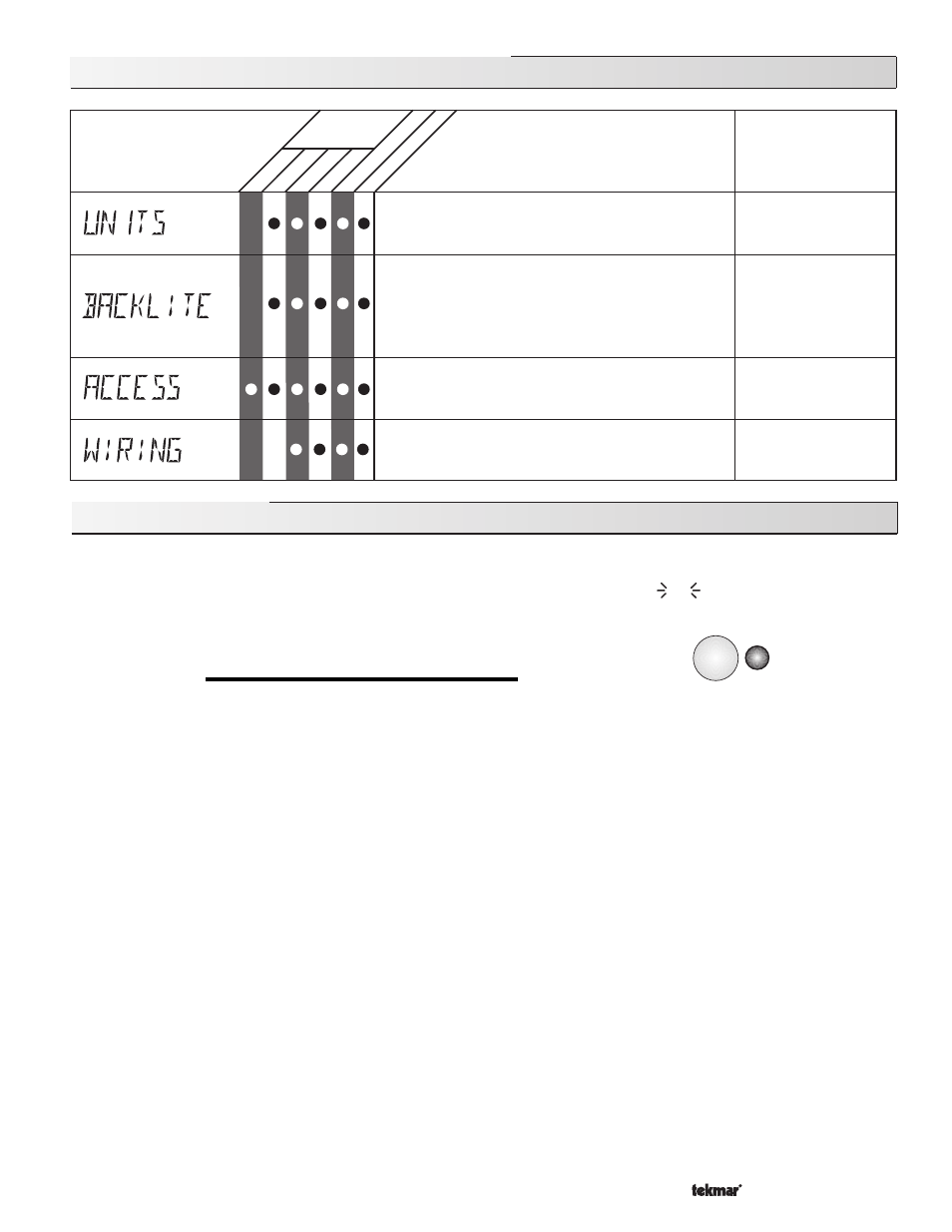
USER
°F, °C
Default =
°F
ADV, INST, USER, LTD
Default = INST
OFF, 30 sec, ON
Default = ON
The operating mode for the back lighting on the LCD
as well as the time of keypad inactivity until the control
automatically returns to the default display.
BACKLITE = OFF (returns after 10 seconds)
BACKLITE = 30 s (returns after 30 seconds)
BACKLITE = ON (returns after 90 seconds)
The units of measure that all of the temperatures are
to be displayed.
The access level that is to be used by the RTU.
DIP switch =
Unlock
Displays which
tn1 terminal on the 369 this RTU is
connected to.
RTU1. . . RTU6
LT
D
INST ADV
Range
Access
Level
Description
Item Field
R
TU 062
R
TU 063
not testing
testing
testing paused
Test
off
red
red
Testing the Control
The Zone Control 369 has a built in test routine which is used to test the
main control functions. The 369 continually monitors the sensors and
displays an error message whenever a fault is found. See the following
pages for a list of the 369’s error messages and possible causes. When
the
Test button is pressed, the test light is turned on. The individual out-
puts and relays are tested in the following sequence.
TEST SEQUENCE
Each step in the test sequence lasts 10 seconds.
During the test routine, the test sequence is paused by pressing the
Test button. While paused, the control displays the testing step
as well as the word PAUS. If the
Test button is not pressed again for 5 minutes while the test sequence is paused, the control exits
the entire test routine. If the test sequence is paused, the
Test button can be pressed again to advance to the next step. This can
also be used to rapidly advance through the test sequence. To reach the desired step, repeatedly press and release the
Test button
until the appropriate device and segment in the display turn on.
Step 1
- The system pump
(Sys Pmp) relay is turned on for 10 seconds. After 10 seconds, the Sys Pmp relay is shut off.
Step 2
- If COOL MOD is set to ENBL or CTRL, the control turns on the
Cooling relay for 10 seconds. After 10 seconds, the Cooling
relay is shut off.
Step 3
- If zone 1 (tN1 1) is used for a one stage heating zone, the control turns on relay Zn 1 for 10 seconds. After 10 seconds,
the
Zn 1 relay is shut off. If an RTU is not connected to tN1 1, the control skips this step.
Step 4
- If zone 2 (
tN1 2 or Indr 2) is used for a one stage heating zone, the control turns on relay Zn 2 for 10 seconds. After 10
seconds, the
Zn 2 relay is shut off.
- If zone 2 (
tN1 2 or Indr 2) is used for a two stage heating zone, the control turns on relay Zn 1 for 10 seconds. After 10
seconds, the
Zn 1 relay is shut off. The Zn 2 relay is then turned on for 10 seconds. After 10 seconds, the Zn 2 relay is
shut off.
- If an RTU or indoor sensor is not connected to
tN1 2 or Indr 2, the control skips this step.
Step 5
- The control tests relay
Zn 3 using the procedure described in Step 3.
Step 6
- The control tests relay
Zn 4 using the procedure described in Step 4.
Step 7
- The control tests relay
Zn 5 using the procedure described in Step 3.
Step 8
- The control tests relay
Zn 6 using the procedure described in Step 4.
- 01/09
- 01/09