tekmar 369 Zone Control Installation User Manual
Page 15
Copyright © D 369 -10/00
15 of 32
20
21
22
Com tN1
1
Item
Menu
UnOcc 1
°F
View
tN1
2
Ω
Ω
V
4
5
Com Out
Zone 6 (
tN1 6 or Indr 6)
Connect the Com terminal from the RTU to the
Com terminal (28) on the 369. Connect the tN1 terminal from the RTU to the
tN1 6 terminal (30) on the 369. If an indoor sensor is used, connect the two wires from the sensor to the Com and Indr 6
terminals (28 and 31).
Note: If an RTU is connected to tN1 6, an indoor sensor can not be connected to Indr 6.
Two Stage RTU and Indoor Sensor Connections.
RTUs and indoor sensors provide indoor temperature feedback to
the control. An indoor sensor can only be used for the even
numbered zones (i.e. zones 2, 4 and 6).
Note: The wires form the RTU are polarity sensitive. The RTU
does not operate properly if the wires are reversed.
Zone 2 (
tN1 2 or Indr 2)
Connect the Com terminal from the RTU to the
Com terminal
(20) on the 369. Connect the
tN1 terminal from the RTU to the
tN1 2 terminal (22) on the 369. If an indoor sensor is used,
connect the two wires from the sensor to the
Com and Indr 2
terminals (20 and 23).
Note: If an RTU is connected to tN1 2, an indoor sensor can not
be connected to
Indr 2.
Zone 4 (
tN1 4 or Indr 4)
Connect the Com terminal from the RTU to the
Com terminal (24) on the 369. Connect the tN1 terminal from the RTU to the
tN1 4 terminal (26) on the 369. If an indoor sensor is used, connect the two wires from the sensor to the Com and Indr 4
terminals (24 and 27).
Note: If an RTU is connected to tN1 4, an indoor sensor can not be connected to Indr 4.
Zone 6 (
tN1 6 or Indr 6)
Connect the Com terminal from the RTU to the
Com terminal (28) on the 369. Connect the tN1 terminal from the RTU to the
tN1 6 terminal (30) on the 369. If an indoor sensor is used, connect the two wires from the sensor to the Com and Indr 6
terminals (28 and 31).
Note: If an RTU is connected to tN1 6, an indoor sensor can not be connected to Indr 6.
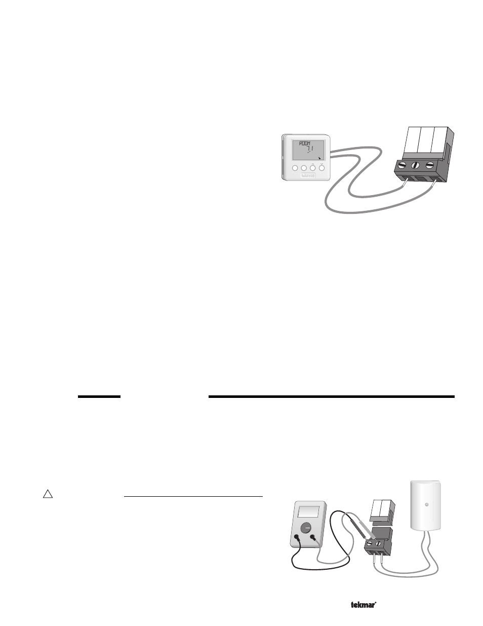
STEP FIVE
TESTING THE WIRING
Each terminal block
must be unplugged from its header on the control before power is applied for testing. To remove a terminal block,
pull it straight down from the control.
The following tests are to be performed using standard testing practices and procedures, and should only be carried out by properly
trained and experienced persons.
A good quality electrical test meter, capable of reading from at least 0 - 300 V (ac) and at least 0 - 2,000,000 Ohms, is essential to
properly test the wiring and sensors.
!
Test The Sensors
In order to test the sensors, the actual temperature at each sensor
location must be measured. A good quality digital thermometer with
a surface temperature probe is recommended for ease of use and
accuracy. Where a digital thermometer is not available, a spare
sensor can be placed alongside the one to be tested and the readings
compared. Test the sensors according to the instructions in the Data
Brochure D 070.
- 01/09
- 01/09