tekmar 369 Zone Control Installation User Manual
Page 14
Copyright © D 369 -10/00
14 of 32
28 29
Com tN1/2
5
Item
Menu
Occ 1
°F
View
Reset Control
Com 10K
Power
Zo
In
Zo
Out
Com
Zone Control
From additional
zone controls
2
3
4
1
2
UnO
Sw
Zo
In
Zo
Out
3
4
Com
Timer Switch
20 21
Com tN1
1
tN1
2
22 23
Indr
2
Item
Menu
UnOcc 1
°F
View
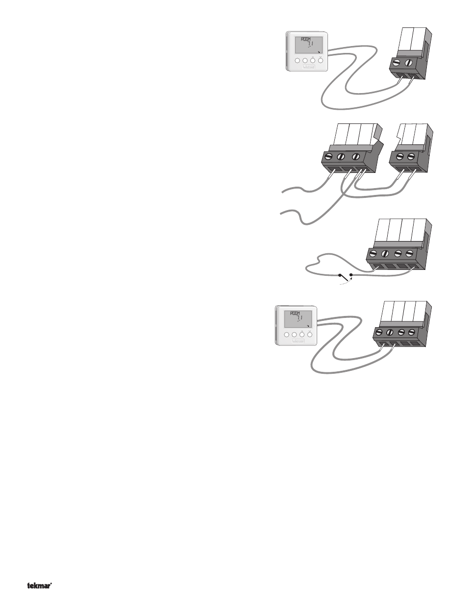
Remote Display Module (RDM) 040 (Optional)
A Remote Display Module (RDM) 040 can be connected to the
tekmar Net
™
(tN1/2) input. Connect the Com terminal from the
RDM to the
Com terminal (28) on the 369. Connect the tN2 terminal
from the RDM to the
tN1/2 5 terminal (29) on the 369. If an RDM is
connected, the 369 is only capable of operating up to 5 zones.
Note: The wires from the RDM are polarity sensitive. The tN2 device
does not operate properly if the wires are reversed.
Zone Control Input and Output
Connect a wire between the
Com (4) terminals on each 369.
Connect the
Zo Out terminal on the first 369 to the Zo In terminal
on the second 369. With several zone controls, connect the
Zo
Out terminal on the second 369 to the Zo In terminal on the third
369 and continue this process for each additional 369. The
Zo Out
terminal on the last 369 in the chain can be connected to the
Zo In
terminal on a tekmar House Control or
10K terminal on a tekmar
Reset Control.
Note: The wires from the zone control are polarity sensitive. The
system will not operate if the wires are reversed.
UnOccupied Switch
If an external timer or switch is used, connect the two wires from
the external dry contact switch to the
Com and UnO Sw (4 and 1)
terminals. When these terminals short together, the control
registers an Unoccupied signal.
One Stage RTU and Indoor Sensor Connections.
RTUs and indoor sensors provide indoor temperature feedback to
the control. An indoor sensor can only be used for the even
numbered zones (i.e. zones 2, 4 and 6).
Note: The wires form the RTU are polarity sensitive. The RTU does
not operate properly if the wires are reversed.
Zone 1 (
tN1 1)
Connect the Com terminal from the RTU to the
Com terminal
(20) on the 369. Connect the
tN1 terminal from the RTU to the
tN1 1 terminal (21) on the 369.
Zone 2 (
tN1 2 or Indr 2)
Connect the Com terminal from the RTU to the
Com terminal (20) on the 369. Connect the tN1 terminal from the RTU to the
tN1 2 terminal (22) on the 369. If an indoor sensor is used, connect the two wires from the sensor to the Com and Indr 2
terminals (20 and 23).
Note: If an RTU is connected to tN1 2, an indoor sensor can not be connected to Indr 2.
Zone 3 (
tN1 3)
Connect the Com terminal from the RTU to the
Com terminal (24) on the 369. Connect the tN1 terminal from the RTU to the
tN1 3 terminal (25) on the 369.
Zone 4 (
tN1 4 or Indr 4)
Connect the Com terminal from the RTU to the
Com terminal (24) on the 369. Connect the tN1 terminal from the RTU to the
tN1 4 terminal (26) on the 369. If an indoor sensor is used, connect the two wires from the sensor to the Com and Indr 4
terminals (24 and 27).
Note: If an RTU is connected to tN1 4, an indoor sensor can not be connected to Indr 4.
Zone 5 (
tN1/2 5)
Connect the Com terminal from the RTU to the
Com terminal (28) on the 369. Connect the tN1 terminal from the RTU to the
tN1/2 5 terminal (29) on the 369.
- 01/09
- 01/09