tekmar 369 Zone Control Installation User Manual
Page 16
Copyright © D 369 -10/00
16 of 32
Ω
V
V
103.5 to 126.5 V (ac)
19
Power
L
N
18
115 V (ac)
L
N
L
Power
17
19
N
Pmp
18
Sys
24 to 230 V (ac)
1-2
6
Com
Zn
8
2
1
7
Zn
M
OR
2
3
4
5
1
Uno
Sw
Zo
In
Zo
Out
Com Out
!
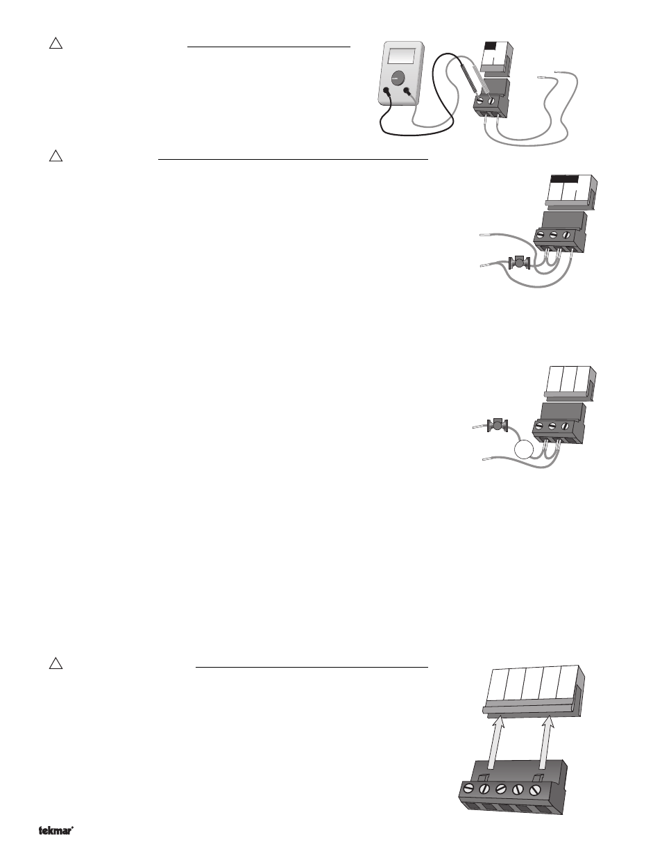
Test The Power Supply
Make sure exposed wires and bare terminals are not in contact with
other wires or grounded surfaces. Turn on the power and measure
the voltage between the
Power L and Power N terminals (18 and
19) using an AC voltmeter. The reading should be between 103.5
and 126.5 V (ac).
!
Test The Outputs
System Pump
If a system pump is connected to the
Sys Pmp terminal (17), make sure power to the
terminal block is off and install a jumper between the
Power L and Sys Pmp terminals
(18 and 17). When power is applied to the
Power L and Power N terminals (18 and
19), the system pump should start. If the pump does not turn on, check the wiring
between the terminal block and pump and refer to any installation or troubleshooting
information supplied with the pump. If the pump operates properly, disconnect the
power and remove the jumper.
Cooling
If a cooling system is connected to the
Cooling terminals (15 and 16), make sure power to the terminal block is off and install a
jumper between the terminals. When the cooling circuit is powered up, the cooling unit should operate. If the cooling unit does
not turn on, refer to any installation or troubleshooting information supplied with the cooling unit. If the cooling unit operates
properly, disconnect the power and remove the jumper.
Zone Pump or Valve
If a zone pump or valve is connected to the
Com 1-2 and Zn 1 terminals (7 and 6),
make sure power to the pump or valve circuit is off and install a jumper between the
Com 1-2 and Zn 1 terminals (7 and 6). When the zone circuit is powered up, the
zone pump should turn on or the valve should open completely. If no response occurs,
check the wiring between the terminal and the pump or valve and refer to any
installation or troubleshooting information supplied with these devices.
If a zone pump or valve is connected to the
Com 1-2 and Zn 2 terminals (7 and 8), follow a similar procedure as described for
the zone 1 relay.
If a zone pump or valve is connected to the
Com 3-4 and Zn 3 terminals (10 and 9), follow a similar procedure as described for
the zone 1 relay.
If a zone pump or valve is connected to the
Com 3-4 and Zn 4 terminals (10 and 11), follow a similar procedure as described for
the zone 1 relay.
If a zone pump or valve is connected to the
Com 5-6 and Zn 5 terminals (13 and 12), follow a similar procedure as described for
the zone 1 relay.
If a zone pump or valve is connected to the
Com 5-6 and Zn 6 terminals (13 and 14), follow a similar procedure as described for
the zone 1 relay.
!
Connecting The Control
Make sure all power to the devices and terminal blocks is off, and remove any
remaining jumpers from the terminals.
Reconnect the terminal blocks to the control by carefully aligning them with their
respective headers on the control, and then pushing the terminal blocks into the headers.
The terminal blocks should snap firmly into place.
Install the supplied safety dividers between the unpowered sensor inputs and the
powered 115 V (ac) or 24 V (ac) wiring chambers.
Apply power to the control. The operation of the control on power up is described in the
Sequence of Operation section of this brochure.
- 01/09
- 01/09