tekmar 369 Zone Control Installation User Manual
Page 13
Copyright © D 369 -10/00
13 of 32
19
Power
N
18
L
115 V (ac)
Cooling Unit
15 16
Cooling
19
18
17
Power
Sys
Pmp
L
N
L
N
115 V (ac)
8
7
6
Zn
1
24 to 230 V (ac)
Com
1-2
Zn
2
M
OR
4
5
Com Out
STEP FOUR
ELECTRICAL CONNECTIONS TO THE CONTROL
The installer should test to confirm that no voltage is present at any of the wires. Push the control into the base and slide it down until
it snaps firmly into place.
!
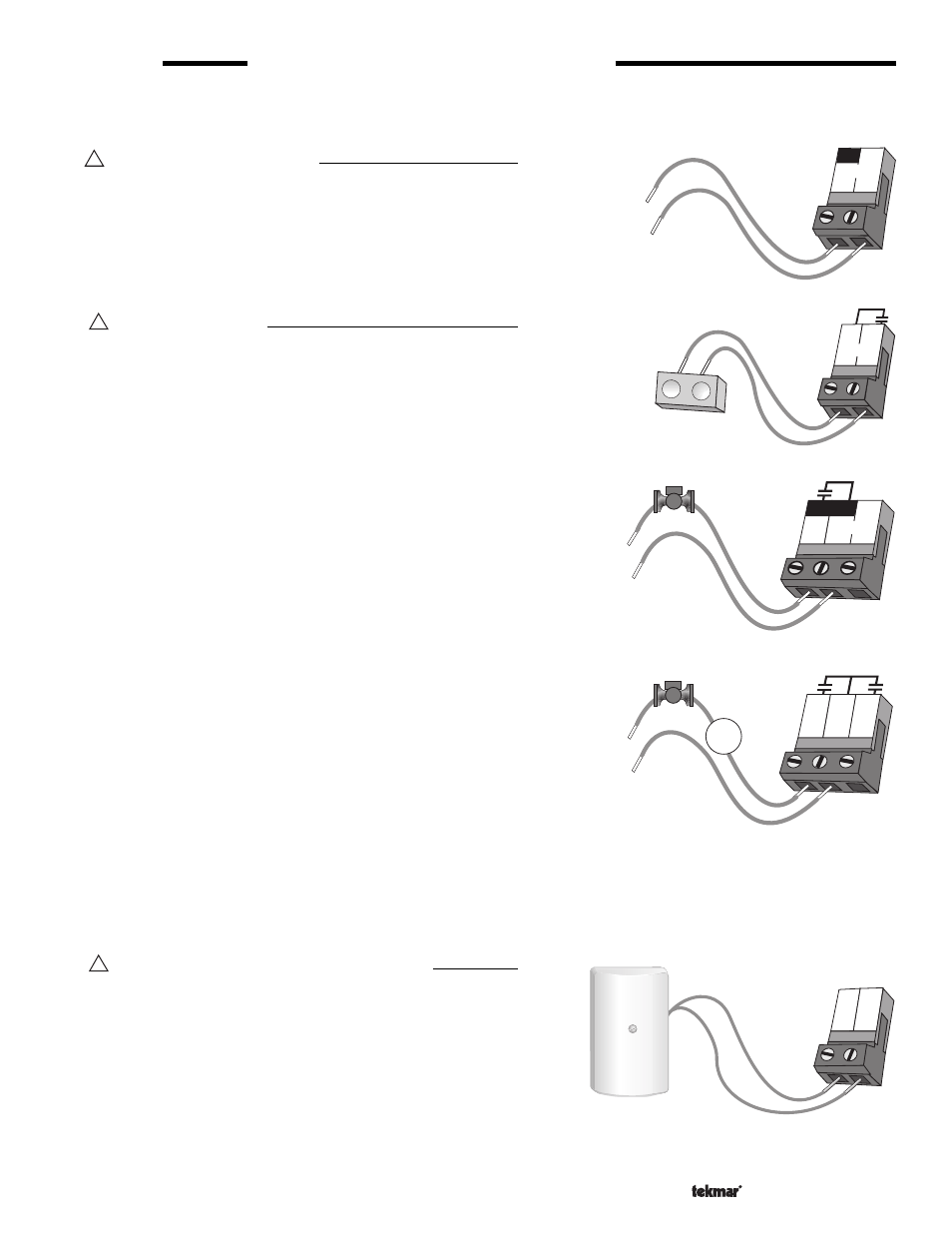
Powered Input Connections
115 V (ac) Power
Connect the 115 V (ac) power supply to the
Power L and Power N
terminals (18 and 19). This connection provides power to the
microprocessor and display of the control. As well, this connection
provides power to the
Sys Pmp terminal (17) from the Power L
terminal (18).
!
Output Connections
Cooling Contact
If a cooling system is used, connect the wires from the cooling unit
to the
Cooling terminals (15 and 16) on the control. The 369 closes
a dry contact between these terminals when cooling is required.
System Pump Contact (
Sys Pmp)
The
Sys Pmp output terminal (17) on the 369 is a powered output.
When the relay in the 369 closes, 115 V (ac) is provided to the
Sys
Pmp terminal (17) from the Power L terminal (18). To operate the
system pump, connect one side of the system pump circuit to the
Sys Pmp terminal (17), and the second side of the pump circuit to
the neutral (N) side of the 115 V (ac) power supply.
Zone Pumps and Zone Valves
Note: The zoning outputs are isolated terminals in the 369. There
is no power available on these terminals from the control. Do not
connect a zone pump and zone valve circuit to the same
Com
terminal.
If zone 1 is used, connect the zone pump or zone valve circuit to
the
Com 1-2 and Zn 1 (7 and 6) terminals on the control.
If zone 2 is used, connect the zone pump or zone valve circuit to
the
Com 1-2 and Zn 2 (7 and 8) terminals on the control.
If zone 3 is used, connect the zone pump or zone valve circuit to
the
Com 3-4 and Zn 3 (10 and 9) terminals on the control.
If zone 4 is used, connect the zone pump or zone valve circuit to the
Com 3-4 and Zn 4 (10 and 11) terminals on the control.
If zone 5 is used, connect the zone pump or zone valve circuit to the
Com 5-6 and Zn 5 (13 and 12) terminals on the control.
If zone 6 is used, connect the zone pump or zone valve circuit to the
Com 5-6 and Zn 6 (13 and 14) terminals on the control.
!
Sensor and Unpowered Input Connections
Do not apply power to these terminals as this will damage
the control.
Outdoor Sensor
Connect the two wires from the Outdoor Sensor 070 to the
Com
and
Out terminals (4 and 5). The outdoor sensor is used by the 369
to measure the outdoor air temperature.
- 01/09
- 01/09