tekmar 275 Boiler Control User Manual
Page 9
9 of 48
© 2012 275_D - 11/12
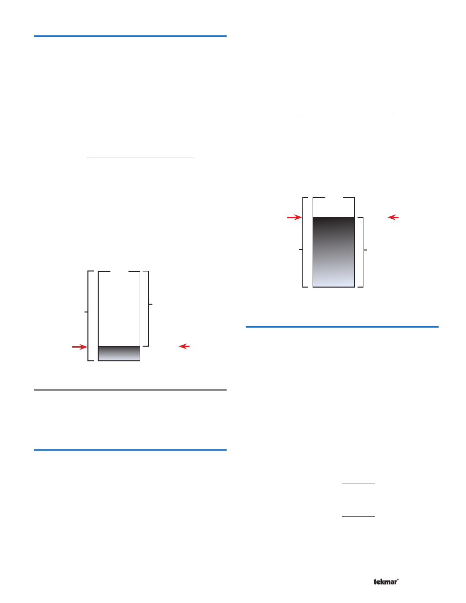
Boiler Minimum Modulation Setting in Adjust Menu
(per boiler)
The Minimum Modulation setting is the lowest modulation
output to obtain low fire. The Minimum Modulation setting
is typically based on the turndown ratio of the boiler. The
control adjusts the modulating output signal from Minimum
Modulation to 0% after the burner turns off and boiler
operation is not required.
To calculate the Minimum Modulation, use the following
formula:
For 0 to 10 V (dc):
Minimum
Modulation
=
0 V (dc) –
Boiler’s Minimum
Input Signal
x 100%
0 – 10 V (dc)
Example:
A boiler requires a 1.8 V (dc) signal to fire the boiler at
low fire. The boiler can be modulated to 10 V (dc) where it
reaches high fire. This means the boiler’s input signal range
is 1.8 to 10 V (dc). The 275 control has an output signal
range of 0 to 10 V (dc).
To make the two signal ranges the same, the Minimum
Modulation required is:
Minimum Modulation = (0 – 1.8) ÷ (0 – 10) x 100% = 18%
Control’s
Output
Signal
Range
Boiler’s
Input
Signal
Range
100%
10 V (dc)
10 V (dc)
0 V (dc)
88%
Boiler’s
Minimum
Input
Signal
Minimum
Modulation
0%
1.8 V (dc)
18%
Minimum Modulation Delay Setting in Adjust Menu
(per boiler)
The Minimum Modulation Delay is the time that the boiler
burner must hold the modulation of the boiler at a minimum
before allowing it to modulate any further.
Boiler Maximum Modulation Setting in Adjust Menu
(per boiler)
The Maximum Modulation defines the maximum output
signal from the control to the boiler burner. It is based on
a percentage of the control’s output signal range. The
maximum modulation setting for boilers with power burners
is typically set to 100%.
For boilers with electronic operators, the boiler’s input signal
range may not match the output signal range of the 275
control. The Maximum Modulation setting limits the control
output range in order to match the boiler’s input range.
To calculate the Maximum Modulation, use the following
formula:
For 0 to 10 V (dc):
Maximum
Modulation
=
0 V (dc) – Boiler’s Maximum
Input Signal
x 100%
0 – 10 V (dc)
Example:
A boiler’s input signal range is 0 to 9 V (dc). The 275
control has an output signal range of 0 to 10 V (dc). To
make the two signal ranges the same, the Maximum
Modulation required is:
Maximum Modulation = (0 – 9) ÷ (0 – 10) x 100% = 90%
Control’s
Output
Signal
Range
Boiler’s
Input
Signal
Range
100%
10 V (dc)
9 V (dc)
0 V (dc)
0 V (dc)
88%
Boiler’s
Maximum
Input
Signal
Maximum
Modulation
0%
Minimum and Maximum Boiler Outputs (MBH)
Setting in Adjust Menu
(per boiler)
In order to accommodate different boiler capacities in the
same system, a minimum and maximum boiler output
for each boiler can be set. This allows the control to
properly operate the boilers using either sequential or
parallel modulation. Each boiler typically has a rating plate
that specifies the minimum and maximum output. This
information is also available in the boiler manual.
The minimum and maximum boiler output is expressed
in MBH. 1 MBH = 1,000 BTU / hour. The range is from 1
MBH to 1,999 MBH.
For example, if a boiler has a maximum output of 100,000
BTU / hr and a minimum output of 20,000 BTU / hr (turn
down ratio of 5):
Maximum Boiler Output =
100,000 = 100 MBH
1,000
Minimum Boiler Output =
20,000 = 20 MBH
1,000