Terminals 1 - 6, Terminals 23 - 26 – tekmar 275 Boiler Control User Manual
Page 24
©
2012 275_D
-
11/12
24
of
48
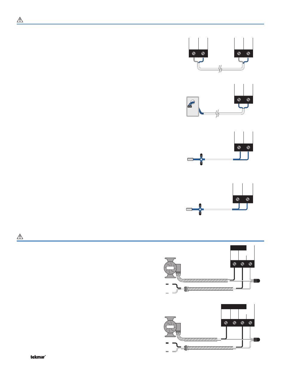
Non-Powered Input Connections
Terminals 1 - 6
tN4
Terminals 1 and 2 provide a tN4 connection for tN4 devices
on the tN4 bus. Connect terminals 1 (tN4) and 2 (Com) to
the corresponding terminals on the tN4 devices that are
to be connected.
Note: The connection is polarity sensitive. Ensure that
terminal 1 (tN4) is connected to the tN4 terminal on the tN4
device and that terminal 2 (C) is connect to the C terminal
on the tN4 device.
Outdoor Sensor (tekmar 070)
Connect the two wires from the Outdoor Sensor 070
to the Com and Out (2 and 3) terminals. The outdoor
sensor is used by the control to measure the outdoor air
temperature.
Note: If an Outdoor Sensor 070 is connected to a
tekmarNet
®
4 thermostat in the system, it is not required
to be connected to the control.
Boiler Supply Sensor (tekmar 082)
Connect the two wires from the Boiler Supply Sensor 082
to the Com and Boil (5 and 4) terminals. The Boiler Supply
Sensor is used by the control to measure the boiler supply
water temperature.
DHW or Boiler Return Sensor (tekmar 082)
Connect the two wires from the DHW Sensor 082 to the
Com and BRet / DHW (5 and 6) terminals. The DHW
Sensor is used by the control to measure the DHW water
temperature or the DHW Exchange Supply Temperature.
OR
Connect the two wires from the Boiler Return Sensor 082
to the Com and BRet / DHW (5 and 6) terminals. The Boiler
Return Sensor is used by the control to measure the boiler
return temperature.
-
Com
tN4
2
1
tN4
Device
Com
tN4
+
-
Out
Com
3
2
Outdoor
Sensor
070
DHW Sensor 082
OR
Boiler Return Sensor 082
DHW
BRet/
Com
6
5
Sup
Com
Boil
5
4
Boiler Supply Sensor 082
Powered Output Connections
Terminals 23 - 26
Primary Pump P1
The Prim P1 output on terminal (24) is a powered output.
When the relay in the control closes, 115 V (ac) is provided
to the Prim P1 terminal (24) from the Power L terminal (25).
To operate the primary pump P1, connect one side of the
primary pump circuit to terminal (24) and the second side
of the pump circuit to the neutral (Power N) side of the 115
V (ac) power supply.
Primary Pump P2
The DHW / P2 output on terminal (23) is a powered output.
When the relay in the control closes, 115 V (ac) is provided
to the DHW / P2 terminal (23) from the Power L terminal
(25). To operate the primary pump P2, connect one side
of the primary pump circuit to terminal (23) and the second
side of the pump circuit to the neutral (Power N) side of the
115 V (ac) power supply.
N
L
Pump
Pump
L & N
23
24 25
26
DHWPrim Power
P2
P1
L
N
N
L
Pump
Pump
L & N
24 25
26
Prim Power
P1
L
N
Primary
Pump
Backup
Primary
Pump
OR
DHW
Pump