tekmar 275 Boiler Control User Manual
Installation & operation manual, 275_d, Boiler control 275
Boiler Control 275
275_D
11/12
Replaces: 01/12
Installation & Operation Manual
Multi-Staging
1
of
48
©
2012 275_D
-
11/12
The Boiler Control 275 is designed to stage up to four condensing or non-condensing, modulating or on-off boilers using
P.I.D. staging to accurately maintain temperature. The control supports hybrid boiler plants that contain both condensing
and non-condensing boiler groups. Water temperature is controlled by outdoor reset for space heating applications or a
fixed setpoint for Domestic Hot Water (DHW) tank heating or industrial process heating applications. The control will also
accept an analog signal from an Energy Management System (EMS) to control the water temperature. Boiler equal run-time
rotation, pump exercising and stand-by system pump operation increase boiler plant reliability. The control is tekmarNet
®
communication compatible allowing for internet connectivity using an optional Gateway 483.
tN4 Compatible
BTC I Compatible
24 Hour, 5-11, 5-2, 7 Day Schedule
Flow or Combustion Air Proof
Four Modulating or On/Off Boilers
•
•
•
•
•
Equal Run Time Rotation
Primary Pump Sequencing
DHW Operation
Optional DHW Sensor
Setpoint Operation
•
•
•
•
•
Additional functions include:
Setback
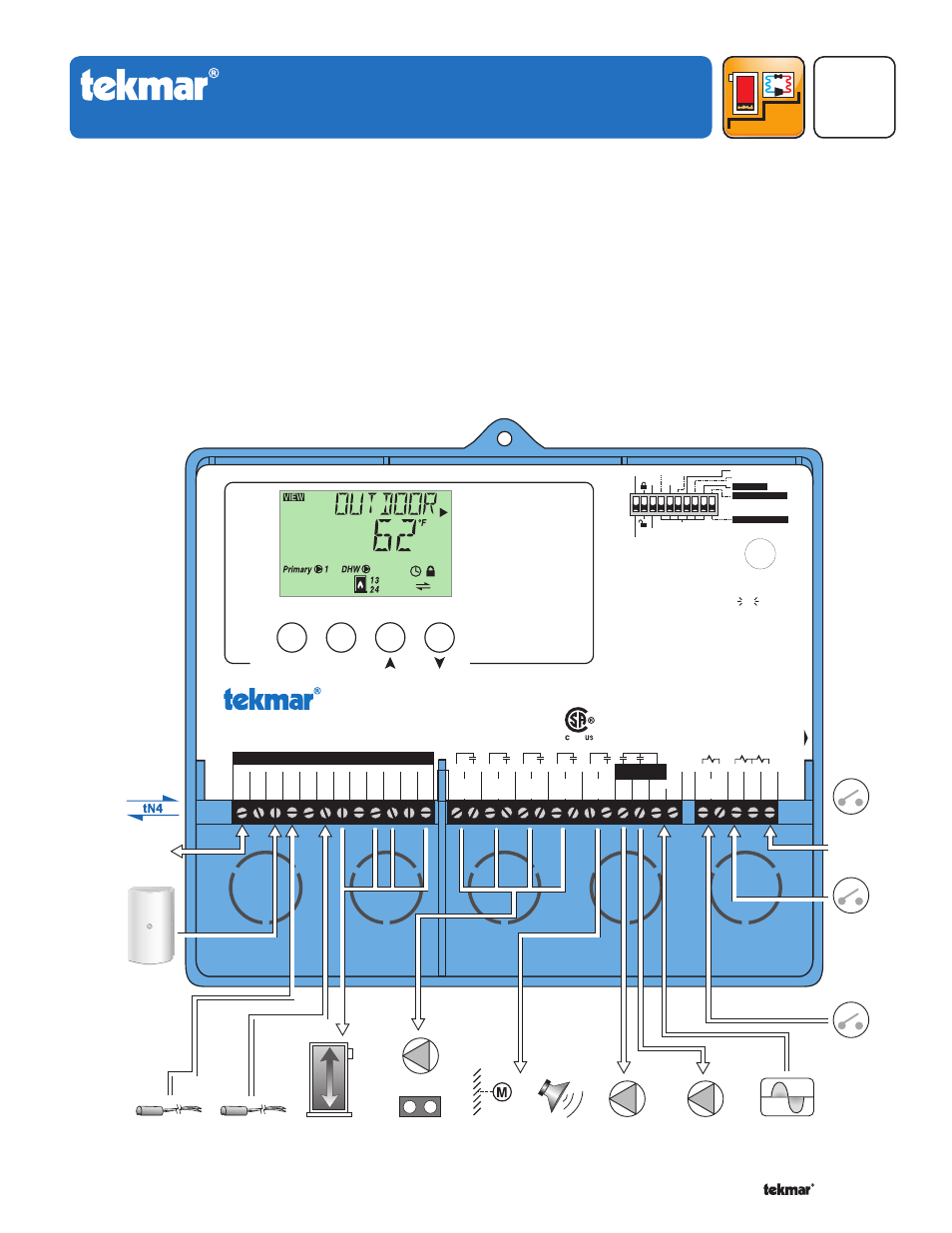
Boiler Control 275
One tN4, Four Modulating Boiler & DHW / Setpoint
Menu
Item
Test
Boiler Demand
DHW / Setpoint Demand
Proof Demand
EMS Input Signal
Priority Override
Power
115 V ±10% 60 Hz 7 VA, 1150 VA max.
Relays
230 V (ac) 5 A 1/3 hp
Demands 20 to 260 V (ac) 2 VA
Designed and assembled in Canada by
tekmar Control Systems Ltd
tektra 1020-01
Meets Class B:
Canadian ICES
FCC Part 15
For maximum heat,
press and hold Test
button for 3 seconds.
not testing
testing
testing paused
off
red
red
BTC I
Off
EMS
Rotate
Fixed Last
Pump Sequencer
Exercise
Off
Demands
Dat
e Code
H2048B
Signal wiring must be rated at least 300 V.
DHW
29
/Setp
Com
30
Dem
Pr.
31
Dem
2
–
5
–
Mod1
1
+
Mod2
3
+
–
+
Mod3
4
+
Mod4
6
+
BRet/
7
Com
8
tN4
12
Boil
9
Out
10
Com
11
Prim
P1
L
N
26
Power
28
27
14
13
Do not apply power
24
DHW
/ P2
23
25
16
15
18
17
20
19
22
21
Fixed Lead
First On / Last Off
First On / First Off
Relay
1
Relay
2
Relay
3
Relay
4
C.A. /
Alert
Boiler
Demand
Sup
DHW
Zone Load Shedding
Input
Universal
Sensor
Included
Input
Universal
Sensor
Included
tN4
Boiler
Bus
Input
Outdoor Sensor
Included
OR
0-10 or 2-10 V (dc)
from EMS
Output
Up to 4
Modulating
Boilers
Input
115 V (ac)
Power Supply
Input
Flow OR
C.A. Proof
Output
Up to 4
Boiler Pumps
OR Boiler Enable
Output
DHW Pump
OR
Primary Pump
Output
Combustion
Air Damper
OR Alert
OR
OR
Output
Primary
Pump
Input
DHW OR
Setpoint
Demand
Signal
Input
Boiler
Demand
Signal