Step five — testing the wiring – tekmar 275 Boiler Control User Manual
Page 26
©
2012 275_D
-
11/12
26
of
48
tN4
Device
Com
tN4
+
-
Out
Com
3
2
Step Five — Testing the Wiring
General
The following tests are to be performed using standard
testing practices and procedures and should only be carried
out by properly trained and experienced persons.
A good quality electrical test meter, capable of reading from
at least 0-300 V (ac), 0-30 V (dc), 0-2,000,000 Ohms, and
testing for continuity is essential to properly test the wiring
and sensors.
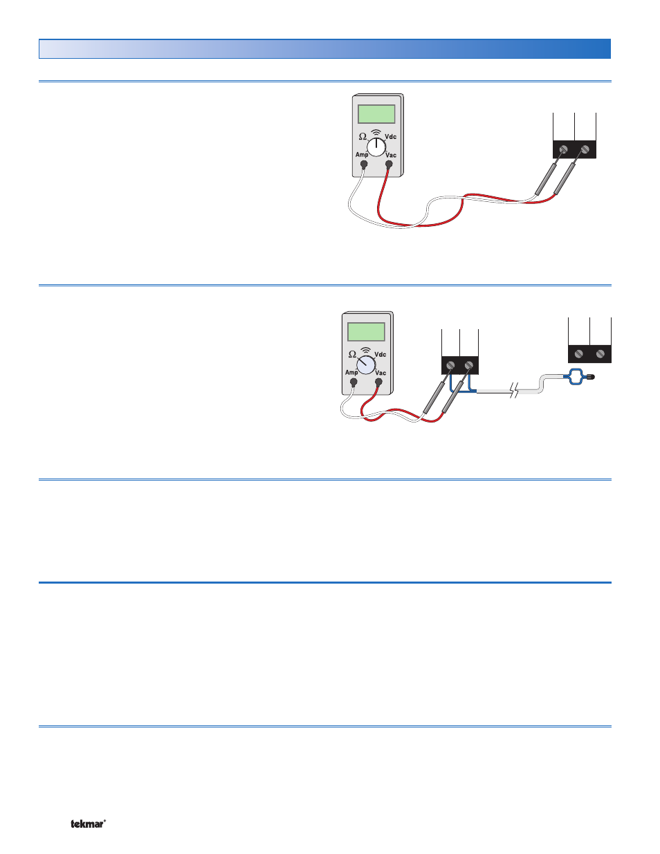
Testing tN4 Network
Terminals 1 – 2
To test the tN4 Network, check the wires for continuity.
1. Disconnect the two wires (tN4 and Com) at one end and
connect them together.
2. Go to the other end of the wires and disconnect them.
3. Using an electrical test meter, check for continuity.
Ω
###
-
Com
tN4
2
1
Boiler
Control
275
Testing the EMS output
Terminals 2 – 3
If an Energy Management System is used, measure the
voltage (dc) between the Com – and the Out + terminals
(2 and 3). When the EMS calls for heat, a voltage between
0 – 10 V (dc) or 2 – 10 V (dc) should be measured at the
terminals.
Testing Modulating Outputs (0-10 V dc)
Terminals 7 – 12
1. Ensure that the control can operate the modulating output
by setting at least one boiler to Auto
2. Remove the front cover from the control.
3. Press the Test Button.
4. When the % output and the boiler symbol are displayed
in the LCD, use an electrical test meter to measure the
(dc) voltage between the appropriate Mod + and the
- terminals (7-8, 8-9, 10-11, 11-12). The reading should
vary between 0 V (dc) and 10 V (dc).
Testing the Sensor Wiring
Terminals 2 – 6
To test the sensors, the actual temperature at each sensor
location must be measured.
Use a good quality digital thermometer with a surface
temperature probe for ease of use and accuracy. Where
a digital thermometer is not available, strap a spare
sensor alongside the one to be tested and compare
the readings.
•
Disconnect each sensor from the control.
Test the sensors resistance according to the instructions
in the sensor Data Brochure D 070.
•
•