tekmar 275 Boiler Control User Manual
Page 17
17 of 48
© 2012 275_D - 11/12
Pump Operation
Section L
Primary Pump Operation
The control includes two primary pump outputs with
capability for sequencing. Primary pump sequencing is
activated through a DIP switch. Only primary pump 1
is operated when pump sequencing is turned off, while
primary pumps 1 and 2 are operated in stand-by mode
when pump sequencing is turned on.
The running times of the primary pumps are logged in the
view menu. To reset these values back to zero, press and
hold the up and down button while viewing this item.
Note: Once primary pump sequencing is selected, DHW
operation is not available. Setpoint operation, however, is
available if primary pump sequencing is selected.
The primary pump(s) will operate when the control receives
an appropriate demand:
External Boiler Demand
tN4 Boiler Demand and that zone’s thermostat has H1
Pump set to On.
DHW Demand and the control is set to DHW Mode 3,
4, or 6.
Setpoint Demand and the control is set to Setpoint Mode
3 or 4.
The primary pump also operates when the control is
completing a DHW Purge.
tN4 thermostats can select whether the primary pump is
required to operate or not. tN4 thermostats also include a
thermal actuator setting which can delay the primary pump
for 3 minutes to allow thermal actuators to open.
Flow Proof
The control includes a flow proof demand in order to prove
flow once a primary pump has turned on. In order for
boiler operation to commence, the proof demand must be
present. A flow proof signal is required at all times during
pump operation. A flow proof is generated by applying a
voltage between 20 and 260 V (ac) across the Flow Proof
terminals (30 and 31). Once voltage is applied, the Proof
Demand indicator is turned on in the LCD.
Once a pump contact is turned on, a flow proof signal must
be present before the flow proof delay has expired.
The flow proof demand is selected by setting the Proof
Demand item in the Adjust menu to F P (flow proof).
A flow proof demand can come from a flow switch, pressure
differential switch, current sensing or power sensing device.
Dem
Dem
Pr.
Com
31
30
L
N
20 to 260 V (ac)
ΔP
Pressure Differential Switch
FS
Flow Switch
KW
Power Sensing Device
Amp Current Sensing Device
•
•
•
•
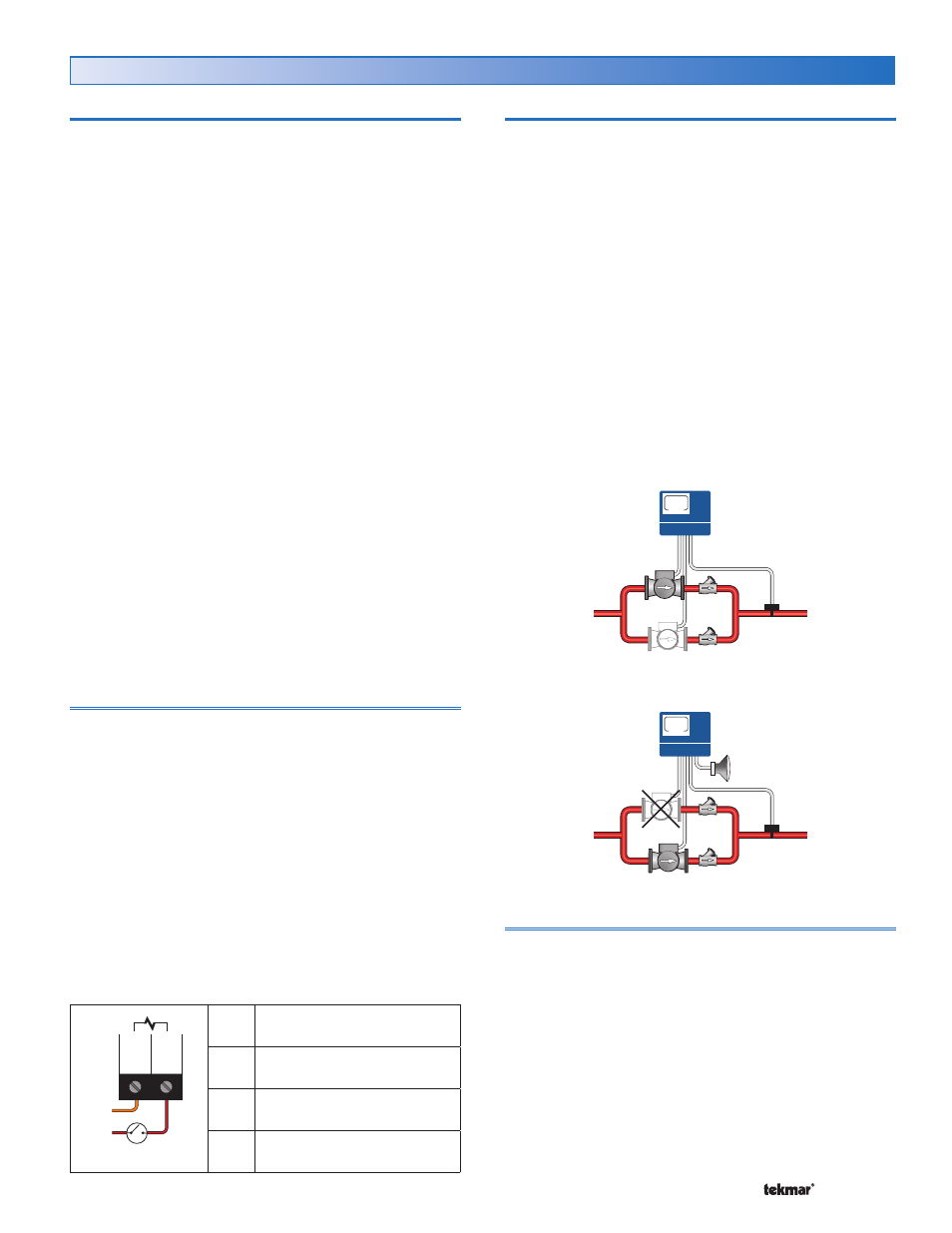
Stand-by Operation
The control only operates one primary pump at a time. A
flow proof device can be used to detect when stand-by
pump operation is required.
When a demand is registered, the lead pump is activated,
and the control waits for flow to be established within the
flow proof delay time.
If no flow is established, the lead pump is de-activated,
the lag pump is activated and the control waits again for
the flow to establish within the flow proof delay time.
If again no flow is established, the lag pump is de-activated
and the control stops operation until the error is cleared.
Verify that the pumps and flow proof device are working
correctly before clearing the error.
If the lead pump establishes flow, and fails during
operation, the lag pump is activated.
If at any time, one or both pumps fail to prove flow, an
error message is displayed.
Normal Operation
On
Flow Proof
Device
Off
275
Stand-by Pump Operation
Failed
Optional
Alert
Flow Proof
Device
On
275
Flow Proof Delay Setting in Adjust Menu
The control waits a period of time to receive a flow proof
demand from the time the primary pump turns on. If the
control does not receive a flow proof demand within that
period of time, the primary pump turns off and the stand-by
primary pump (if active) turns on. The control then waits
that period of time again for the stand-by primary pump to
prove flow. If flow is not proven, the stand-by pump turns
off. The period of time is set through the Proof Demand
‘Pump’ DLY item in the Adjust menu and it is adjustable
between 10 seconds and 3 minutes.
•
•
•
•
•