Warranty, Strobe power supply, Optional strobe power supply diagnostic panel – SoundOff Signal Photon Power Supply User Manual
Page 3
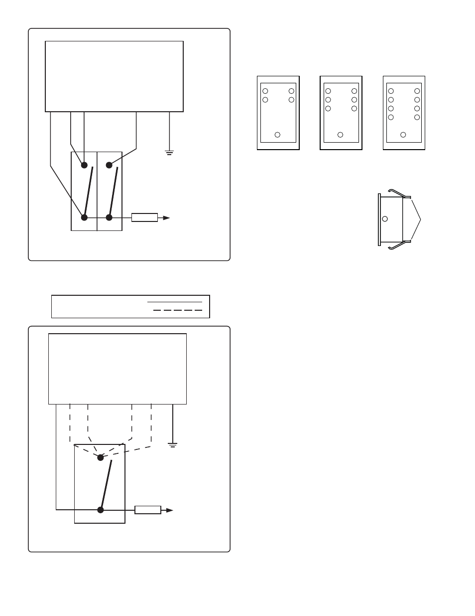
Figure D.
Special Pattern Options On/Off Switching
WARRANTY
SoundOff Signal warranties the Photon Strobe Power Supply
for five (5) years from the date of purchase to the original pur-
chaser against any manufactured defects or workmanship.
This warranty is a 100% replacement value warranty. It ap-
plies only to units installed according to manufacturer’s in-
stallation instructions and operated within the units specifica-
tions.
Warranty is void if the unit was installed incorrectly or mali-
ciously damaged.
All warranty claims must be accompanied by a dated proof of
purchase.
SoundOff Signal retains the right to be the sole mediator of
what constitutes defects in performance or manufacturing.
STROBE POWER SUPPLY
15 AMP
FUSE
SPST ON/OFF SWITCH
(REAR VIEW)
(+) 8-30 VDC
RED (+)
GREEN
BLUE
GREY
(BROWN)
YELLOW
BLACK (-)
Figure C.
Quad Flash All Heads High/Low Switching
STROBE POWER SUPPLY
15 AMP
FUSE
TWO SPST ON/OFF SWITCHES
(REAR VIEW)
(+) 8-30 VDC
RED (+)
GREEN
BLUE
GREY
(BROWN)
BLACK (-)
DIRECT CONNECTION
OPTIONAL CONNECTION
OPTIONAL STROBE POWER SUPPLY
DIAGNOSTIC PANEL
FOR USE WITH DIAGNOSTIC EQUIPPED POWER SUPPLIES ONLY
MOUNTING OPTIONS:
1.
Display will snap into any existing
panel with a 22.5mm x 40mm hole.
2.
Remove tabs from the back of
display and adhere to mounting
surface using double sided tape.
INSTALLATION:
Plug the RJ11 end of the cable into the Diagnostic Display.
Route the other end of the cable to the Power Supply and
connect the 4-pin Amp Connector.
OPERATION:
Each numbered LED will flash with the corresponding
numbered Strobe Tube showing everything is operational. If
an LED light stay ON, instead of flashing, there is a problem
with that particular Strobe Tube or Strobe Cable. Low
Intensity LED will indicate when the Power Supply is low
power.
To Reduce EMI emissions, ONE end of the shield (drain wire)
of the extension cable connecting the output of the power
supply to the Lighthead should be connected to ground.
Make sure ONLY ONE END of the shield is tied to ground.
The other end needs to be taped or cut.
TABS
4 - HEAD
PEDIPNL4/
PEDIPNL4WP
1
3
2
4
LOW
INTENSITY
1
3
2
4
5
6
LOW
INTENSITY
1
3
2
4
5
6
LOW
INTENSITY
7
8
6 - HEAD
PEDIPNL6/
PEDIPNL6WP
8 - HEAD
PEDIPNL8