Strobe power supply – SoundOff Signal Photon Power Supply User Manual
Page 2
NOTE
It is important to follow the correct color code when
inserting the pins into the connectors.
5.
Connect the cables to the strobe light heads.
6.
Next, plug the other end of the cable into the Light Head
Output Socket on the Strobe Power Supply.
7.
Using Figure E, select a flash pattern and determine which
flash control wires will need to be used. The grey(brown) wire
controls the day/night (high/low) intensity feature of the power
supply, see Figure C. The high/low intensity feature allows
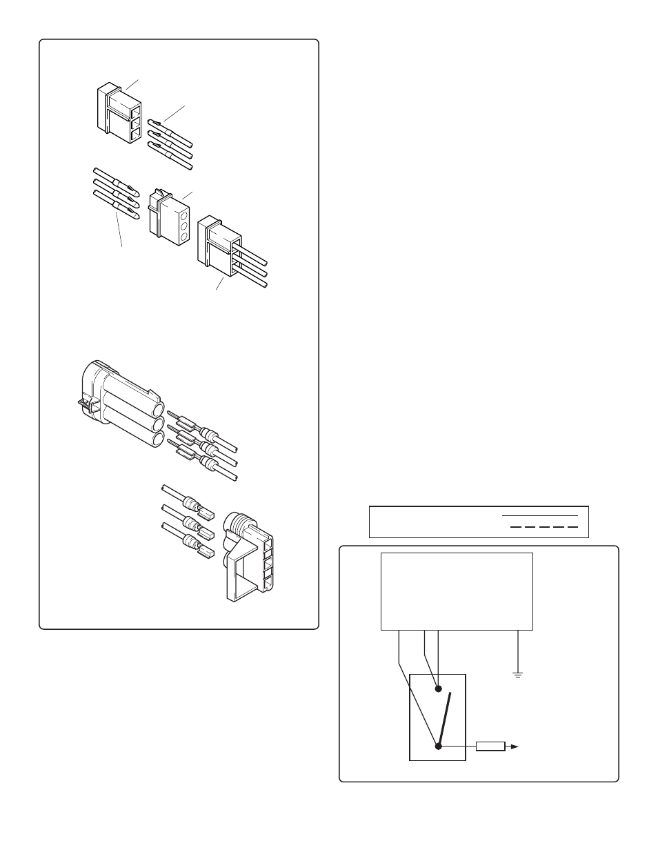
Figure A.
MALE AMP CONNECTOR
(to be mated with the AMP output
socket on the Power Supply)
Insert wires with male pins into
the proper locations in the male
AMP connector:
RED WIRE - HOLE #1
BLACK WIRE - HOLE #2
WHITE WIRE - HOLE #3
FEMALE AMP CONNECTOR
Insert wires with female pins into
the proper locations in the female
AMP connector:
RED WIRE - HOLE #1
BLACK WIRE - HOLE #2
WHITE WIRE - HOLE #3
AMP WIRE HARNESS
(attached to Strobe Light Head)
Insert wires with male pins into
the proper locations in the male
WP connector:
RED WIRE - HOLE A
BLACK WIRE - HOLE B
WHITE WIRE - HOLE C
Insert wires with female pins into
the proper locations in the female
WP connector:
RED WIRE - HOLE A
BLACK WIRE - HOLE B
WHITE WIRE - HOLE C
ETPN475 - Amp Connectors
ETPN475WP - WP Connectors
the strobe lights to be switched into low power or reduced
intensity. This feature is useful for night time use. When the
grey(brown) wire is powered, the power supply is switched to
low intensity. When the power is removed, the power supply
switches to high intensity mode. Use 18 gauge wire to ex-
tend the flash control wires to a customer supplied switch as
shown in Figures B, C and D.
8.
Connect the red wire to the positive (+) side of the battery
making sure to place a customer supplied 15 Amp fuse at the
battery. Connect the black wire to the negative (-) side of the
battery or to the vehicle chassis.
NOTE
To extend the power (+) and ground (-) wires, use the
following as a guide.
1 to 10 ft. use 16 AWG wire
10 to 20 ft. use 14 AWG wire
20 to 30 ft. use 12 AWG wire
30 to 50 ft. use 10 AWG wire
Figures B, C and D show some of the standard switch control
options that can be easily wired to complete a Strobe Light
System.
Figure B shows a high/off control system that quad flashes
all heads.
Figure C shows a high/low control system that quad flashes
all heads.
Figure D shows how any flash option could be installed de-
pending on which flash control wire(s) are attached to the
switch.
Figure B.
Quad Flash All Heads High/Off Switching
SPST ON/OFF SWITCH
(REAR VIEW)
15 AMP
FUSE
(+) 8-30 VDC
RED (+)
GREEN
BLUE
BLACK (-)
STROBE POWER
SUPPLY
DIRECT CONNECTION
OPTIONAL CONNECTION