General, Wiring, Control module wiring – SoundOff Signal TrafficMaster User Manual
Page 2
LED TRAFFIC MASTER Page 4
GENERAL
All devices should be mounted in accordance with the manufacturer’s in-
structions and securely fastened to vehicle elements of sufficient strength
to withstand the forces applied to the device.
WIRING
Do not use insulation displacement connectors (e.g. 3M Scotchlock type
connectors). Route wiring using grommets and sealant when passing
through compartment walls. High ambient temperatures (e.g. under-hood)
will significantly reduce the current carrying capacity of wires, fuses, and
circuit breakers. Use “SXL” type wire in engine compartment. Minimize
the number of splices to reduce voltage drop. All wiring should conform to
the minimum wire size and other recommendations of the manufacturer
and be protected from moving parts and hot surfaces. Looms, grommets,
cable ties, and similar installation hardware should be used to anchor and
protect all wiring.
Particular attention should be paid to the location and method of making
electrical connections and splices to protect these points from corrosion and
loss of conductivity. Ground terminations should only be made to substantial
chassis components, preferably directly to the vehicle battery.
The user should install a fuse sized to approximately 125% of the maximum
amp capacity in the supply line and each switched circuit to protect against
short circuits. For example, a 5 amp fuse should carry a maximum of 4
amps. Circuit breakers are very sensitive to high temperatures and will “false
Page 7
LED TRAFFIC MASTER
CONTROL MODULE WIRING
NOTE
DO NOT USE FUSIBLE LINKS, CIRCUIT BREAKERS
OR GLASS FUSES!!!
1. Choose the ideal mounting location for the Control Module. It fits into any
standard vehicle console that is designed to hold radio or other electronic
equipment. It also works well when mounted under the vehicle’s dash.
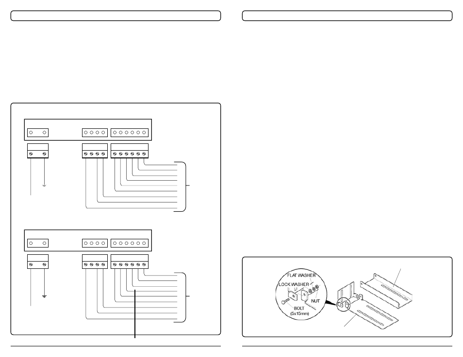
Figure 5. Standard and Optional Wiring Schematics
WIRE
HARNESS
FROM
LIGHT BAR
WIRE
HARNESS
FROM
LIGHT BAR
REAR VIEW OF CONTROL PANEL
REAR VIEW OF CONTROL PANEL
GROUND
+ 12-24 Vdc
GROUND
+ 12-24 Vdc
PURPLE
DK. GREEN
BLUE
LT. GREEN
YELLOW
PINK
RED
BLACK
WHITE
RED
BLACK
RED
BLACK
BLACK
RED
PINK
YELLOW
LT. GREEN
BLUE
DK. GREEN
PURPLE
WHITE
“STANDARD” LED TRAFFIC MASTER WIRING
“OPTIONAL” LED TRAFFIC MASTER WIRING
Figure 1. “L” Bracket Assembly
Heavy Duty Bracket
Standard Brack-