Light module wire harness locations, Nforce led interior lightbar – SoundOff Signal nFORCE Interior User Manual
Page 9
IMPORTANT INFORMATION:
Warning devices are strictly regulated and governed by Federal, State and Municipal ordinances. These devices shall be used ONLY on approved vehicles. It is the sole responsibility of the user of these devices to ensure compliance.
To review our Limited Warranty Statement & Return Policy for this or any SoundOff Signal product, visit our website at
www.soundoffsignal.com/sales-support.
If you have questions regarding this product, contact
Technical Services, Monday - Friday, 8 a.m. to 5 p.m. at 1.800338.7337 (press #4 to skip the automated message).
Questions or comments that do not require immediate attention may be emailed to
SUPERIOR CUSTOMER RELATIONSHIPS. SMARTLY DESIGNED LIGHTING & ELECTRONIC SOLUTIONS.
nFORCE LED Interior Lightbar
ENFWBF(xx)0(x) 5.14
LIGHT MODULE WIRE HARNESS LOCATIONS
REPLACEMENT OF INBOARD MODULES:
1. Disconnect main power.
2. Remove top cover by removing screws.
3. Locate module and remove mounting nuts. Remove module from lightbar.
4. Remove connector from rear of module by carefully pulling connector body from back of module.
5. Push module connector into replacement module ensuring locking latch is seated properly or connector is fully seated.
6. Replace module and hardware that fasten module to shroud.
7. Restore power to bar and test new module to ensure functionality.
8. Replace top cover of bar with screws removed in step 2.
Driver Module Replacement:
a. Verify power has been removed from lightbar before attempting service
b. Remove cover
c. Unplug 3 and / or 6 pin power/data connector(s) and LED module connectors from driver module assembly, noting location.
d. Remove driver module
e. Attach new driver module assembly into housing
f. Plug 3 and/or 6 pin power/data connector(s) and LED module connectors into driver module assembly
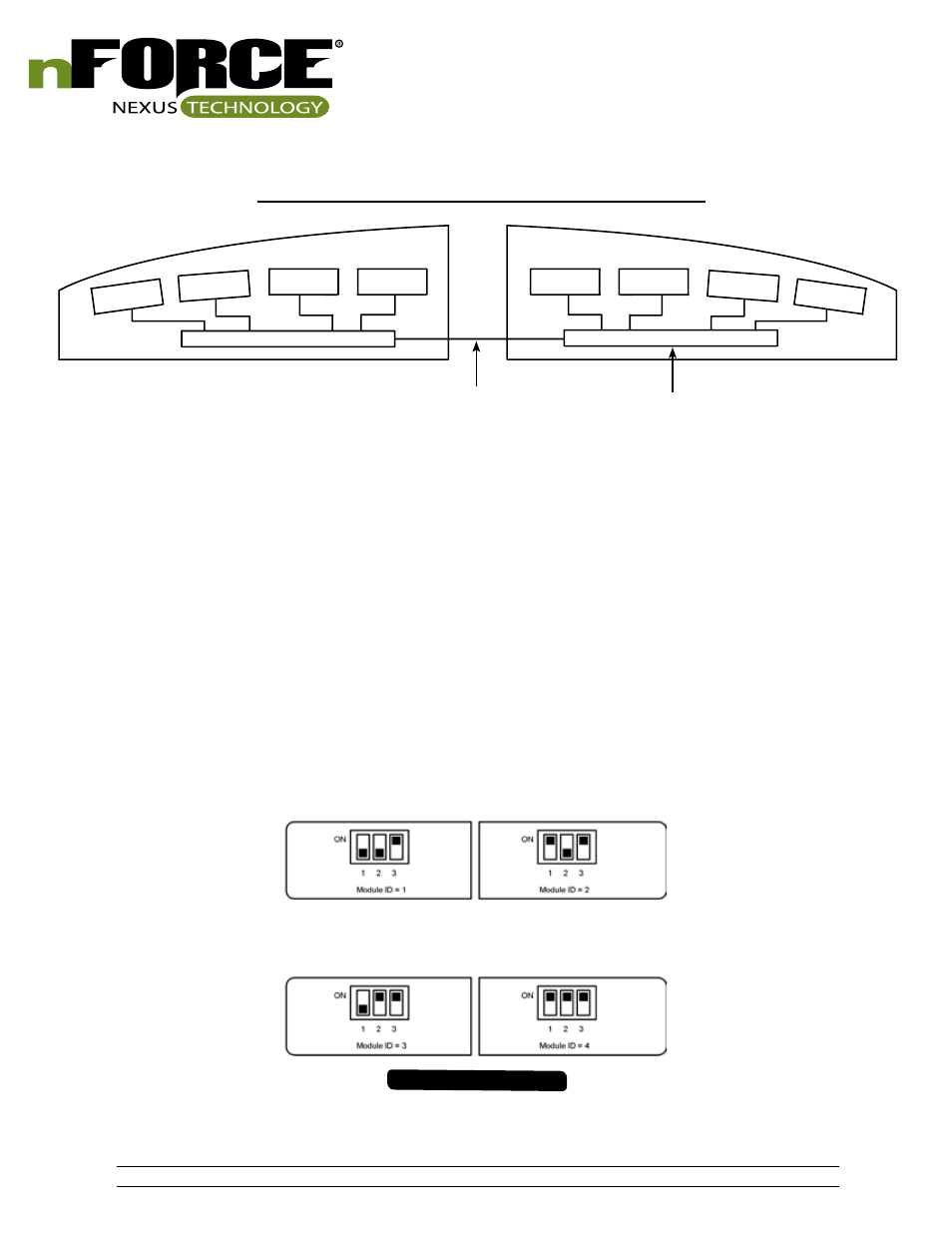
g. Set DIP switch according to lightbar location and driver module location as shown below:
h. Apply power to lightbar and verify proper operation.
i. Set Switch #2 on Breakout Box to Down position then to Up position to store configuration into new driver module
j. If lightbar does not function properly, verify DIP switch settings and change if not correct, then repeat step ‘i’
POWER DISTRIBUTION WIRE
9.
DRIVER BOARD
DRIVER SIDE
PASSENGER SIDE
FORWARD FACING
REARWARD FACING
#1
#2
#3
#4
#4
#3
#2
#1