Electrical installation (continued), Flash patterns, Nforce led interior lightbar – SoundOff Signal nFORCE Interior User Manual
Page 5
IMPORTANT INFORMATION:
Warning devices are strictly regulated and governed by Federal, State and Municipal ordinances. These devices shall be used ONLY on approved vehicles. It is the sole responsibility of the user of these devices to ensure compliance.
To review our Limited Warranty Statement & Return Policy for this or any SoundOff Signal product, visit our website at
www.soundoffsignal.com/sales-support.
If you have questions regarding this product, contact
Technical Services, Monday - Friday, 8 a.m. to 5 p.m. at 1.800338.7337 (press #4 to skip the automated message).
Questions or comments that do not require immediate attention may be emailed to
SUPERIOR CUSTOMER RELATIONSHIPS. SMARTLY DESIGNED LIGHTING & ELECTRONIC SOLUTIONS.
nFORCE LED Interior Lightbar
ENFWBF(xx)0(x) 5.14
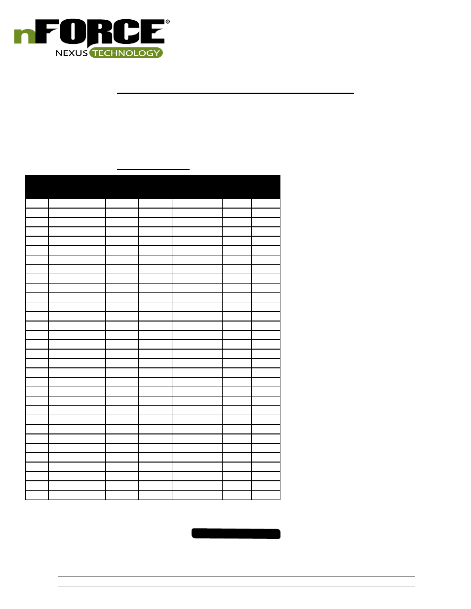
*fpm=Flashes per Minute
**fps=Flashes per Second
FLASH PATTERNS
#
Name
SAE
Compliant
Timing
Color
Sequence
fpm
fps
1
Random Single #1
Yes
#1
Variable
-
-
2
Random Single #2
No
#1
Variable
-
-
3
Quint
Yes
#1
Alternating
70
1.2
4
Quad 2
Yes
#1
Variable
-
-
5
Q-Switch
Yes
#1
Variable
-
-
6
Double
Yes
#1
Alternating
115
1.9
7
Power Pulse
Yes
#1
Alternating
180
3.0
8
RoadRunner
Yes
#1
Alternating
115
1.9
9
SlowRunner
Yes
#1
Alternating
70
1.2
10
Warp
No
#1
Alternating
350
5.8
11
Inter-cycle
No
#1
Alternating
-
-
12
Warp 1, 2, 3
No
#1
Variable
-
-
13
E-Single
Yes
#1
Alternating
125
2.1
14
E-Double
Yes
#1
Alternating
125
2.1
15
E-Triple
Yes
#1
Alternating
125
2.1
16
Random Duo #1
Yes
#1/2
Variable
-
-
17
Random Duo #2
No
#1/2
Variable
-
-
18
Quint Duo
Yes
#1/2
Alternating
70
1.2
19
Quad 2 Duo
Yes
#1/2
Variable
-
-
20
Q-Switch Duo
No
#1/2
Variable
-
-
21
Double Duo
Yes
#1/2
Alternating
115
1.9
22
Power Pulse
Yes
#1/2
Alternating
180
3.0
23
RoadRunner Duo
Yes
#1/2
Alternating
115
1.9
24
SlowRunner Duo
Yes
#1/2
Alternating
70
1.2
25
Warp Duo
No
#1/2
Alternating
350
5.8
26
Inter-cycle Duo
No
#1/2
Alternating
-
-
27
Warp 1, 2, 3, Duo
No
#1/2
Variable
-
-
28
Dual Color Flash 1
No
#1/2
Variable
-
-
29
Dual Color Flash 2
No
#1/2
Variable
-
-
30
Impact
No
#1/2
Variable
-
-
31
Explosion
No
#1/2
Variable
-
-
32
Tri Color Flash 1
No
#1/2/3
Alternating
-
-
ELECTRICAL INSTALLATION (CONTINUED)
Warning Flash Pattern Configuration:
a. Set Switch #2 on Breakout box to down position (Switch #1 must be in Up position)
b. Apply voltage to the activation wire of the function which requires pattern to be changed (i.e. Front Corner, Takedown, Left Alley, etc.)
c. Apply voltage to the Mode activation wire to configure mode 2 flash patterns, leave Mode activation wire floating to configure mode 1
flash patterns
d. Momentarily apply voltage to the pattern select wire to change the warning flash pattern
e. Set Switch #2 on Breakout box to up position to save settings and return light-bar to normal operating mode
5.
NOTE: Takedown and Alley light patterns
are limited to pattern #1 – 15