Controller and wire harness instructions, Light module wire harness locations – SoundOff Signal Apex LED User Manual
Page 13
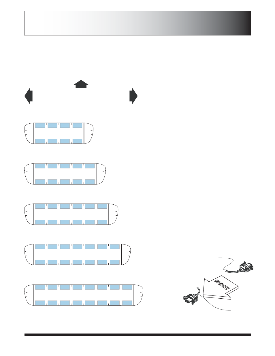
LIGHT MODULE WIRE HARNESS LOCATIONS
CONTROLLER AND WIRE
HARNESS INSTRUCTIONS
Colors shown indicate color coded labels on
wiring harness.
White is for Take Down 1 lights. Orange (if
available) is for Take Down 2 lights. Replace
color indicated on diagram with white (or
Orange) labeled wire.
If modules are being replaced in the field make
sure they are reinstalled with single wire
connectors to FRONT of vehicle. See below.
Green
Single Wire
(Front)
Red, Blue Double
Wire (Rear)
DRIVER
SIDE
PASSENGER
SIDE
FRONT
Page 13
REPLACEMENT OF INBOARD AND
END (CORNER) MODULES:
1. Disconnect main power.
2. Remove top cover by removing 3 torx drive
screws.
3. Locate module and remove mounting screws or
locknuts. Pull or slide module from lightbar.
4. Remove connector from rear of module by
carefully disengaging locking latch and pull
connector from back of module.
5. Push module connector into replacement module
ensuring locking latch is seated properly.
6. Replace module and hardware that fasten module
to base extrusion.
7. Restore power to bar and test new module to
ensure functionality.
8. Replace top cover of bar with screws removed in
step 2.
11
12
13
14
31
32
33
34
11
12
13
14
15
31
32
33
34
35
11
12
13
14
15
16
31
32
33
34
35
36
11
12
13
14
15
16
17
31
32
33
34
35
36
37
11
12
13
14
15
16
17
18
31
32
33
34
35
36
37
38
Green
Red
Red
Red
Red
Red
Red
Red
Red
Red
Red
Red
Red
Red
Red
Red
Red
Green
Green
Green
Green
Green
Green
Green
Green
Green
Green
Green
Green
Green
Green
Green
Green
Green
Green
Green
Blue
Blue
Blue
Blue
Blue
Blue
Blue
Blue
Blue
Blue
Blue
Blue
Blue
Blue
Blue
Blue
w
o
l
l
e
Y
w
o
l
l
e
Y
Yellow
Yellow
Yellow
Yellow
w
o
l
l
e
Y
w
o
l
l
e
Y
37” Bar
43” Bar
50” Bar
63” Bar
56.5” Bar