Standstill (under-speed) monitoring applications – Banner Safe Speed Monitoring Modules User Manual
Page 9
Number of pulses per minute at a speed in meters per minute: sensing points/meter × meters/minute
For this example, the number of pulses = 4 pulses/meter × 60 meters/minute = 240 pulses/minute.
To detect a speed greater than 1 meter/second, the switching point must be set slightly higher than 240 ipm; for 4 sensing points: 4
pulses per meter.
Rotational Motion Applications
Depending on the number of sensing points at the motor, the ipm (impulses per minute) can be a multiple of the motor rpm. Use the
following formula to calculate the number of impulses per minute the Module will see from the two sensor outputs: rpm x number of
sensing points per sensor = ipm
If each sensor sees one sensing point per motor turn, then rpm = ipm.
Examples:
• At 1000 rpm with 1 sensing point per turn per sensor: 1000 x 1 = 1000 ipm
• At 1000 rpm with 2 sensing points per turn per sensor: 1000 x 2 = 2000 ipm
Because more sensing points per sensor are interpreted by the Module as a higher rpm, the more sensing points used, the closer the
switch point can be set to 0 rpm.
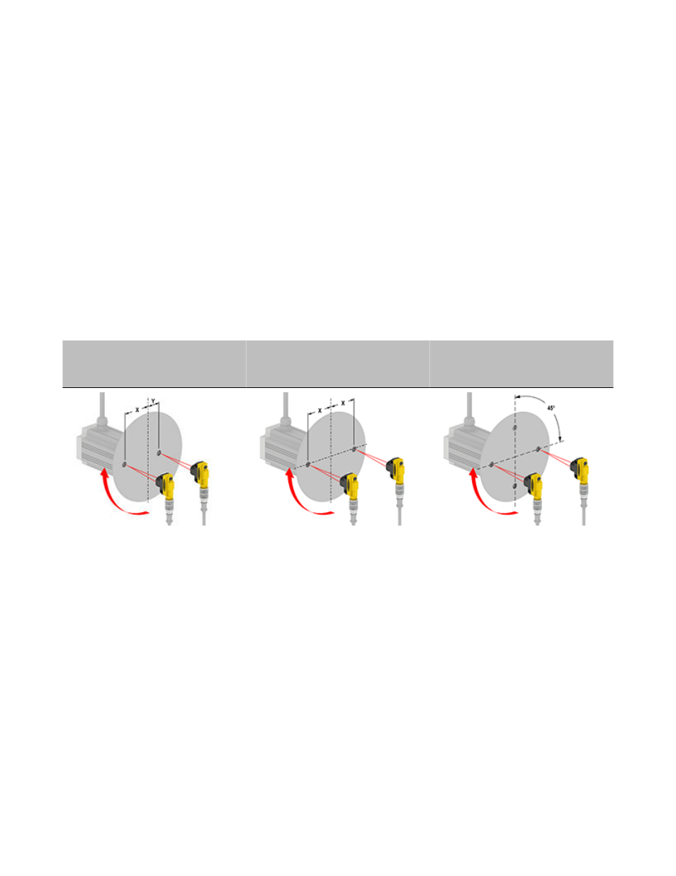
NOTE: Both sensors must always sense their sensing points at the exact same time, so that the two Module inputs receive the pulses at
the same time. If two sensing points are used per sensor, they must be offset by 180°. If four sensing points are used, they must be
offset by 90° of each other (see figures).
Each sensor sends one pulse per revolu-
tion to the Module (500 rpm = 500 ipm).
Each sensor sends two pulses per revo-
lution to the Module (500 rpm = 500 x 2 =
1,000 ipm).
Each sensor sends four pulses per revo-
lution to the Module (500 rpm = 500 x 4 =
2,000 ipm).
Two sensing points at different distances
from the center of the disk.
Two sensing points at the same distance
from the center of the disk
Four sensing points at the same distance
from the center of the disk
Standstill (Under-speed) Monitoring Applications
Because the pulses that define the detected speed are created by sensors that monitor the moving or rotating part (work piece or tool),
speed sensing is independent of the supply voltage of the monitored motor.
The two input channels are factory pre-adjusted for reliable switching simultaneity of the sensor inputs. A channel fine-tuning potentiome-
ter inside the Module housing (behind the front cover) provides exact simultaneity.
SSM-FM-11A... Safe Speed Monitoring Modules
P/N 140782_web
rev. C
www.bannerengineering.com - tel: 763-544-3164
9