Banner Safe Speed Monitoring Modules User Manual
Page 5
Reset and Startup Conditions
The Module works only in automatic reset mode. In order for the Module to
switch to RUN mode for normal operation, the Y1 - Y2 feedback input
must be closed during power-up.
The Module typically requires two to three seconds after power ON to
evaluate the signals from the two sensors and to decide if the number of
incoming signals/pulses is above or below the set switch point value. After
three seconds, if the Module detects a number of pulses per minute below
the set value, the relays energize and the output contacts turn ON, indicat-
ing a standstill condition. If the machine being monitored and the Module
are powered up at the same time, the machine has only three seconds to
come up to speed, or the Module detects a standstill condition. If the ma-
chine requires more than three seconds, power up the machine first, then
the Module, after the appropriate delay.
When each of the internal relays is energized, its corresponding LED turns
ON green. Both relay outputs activate only if both inputs reach the ena-
bling conditions within approximately two seconds. If the signals are not
received within two seconds (e.g., because of a defective sensor or be-
cause the channels did not switch simultaneously), the output contacts will
not turn ON, and power to the Module must be cycled.
SSM-FM-11A10
or
SSM-FM-11A20
Sensor 2
24V ac/dc
0 V
K1
A
4 A max.
K2
A
K1
B
K2
B
K1
C
K2
C
Y1
MSC1
MSC
Monitor
Contacts
or Jumper
MSC2
+24V
0V
PNP
Signal
Out
13
S2+
S2s
S2-
Sensor 1
+24V
0V
PNP
Signal
Out
S1+
A2
A1
S1s
S1-
14
24
31
32
Y2
23
See External Device
Monitoring
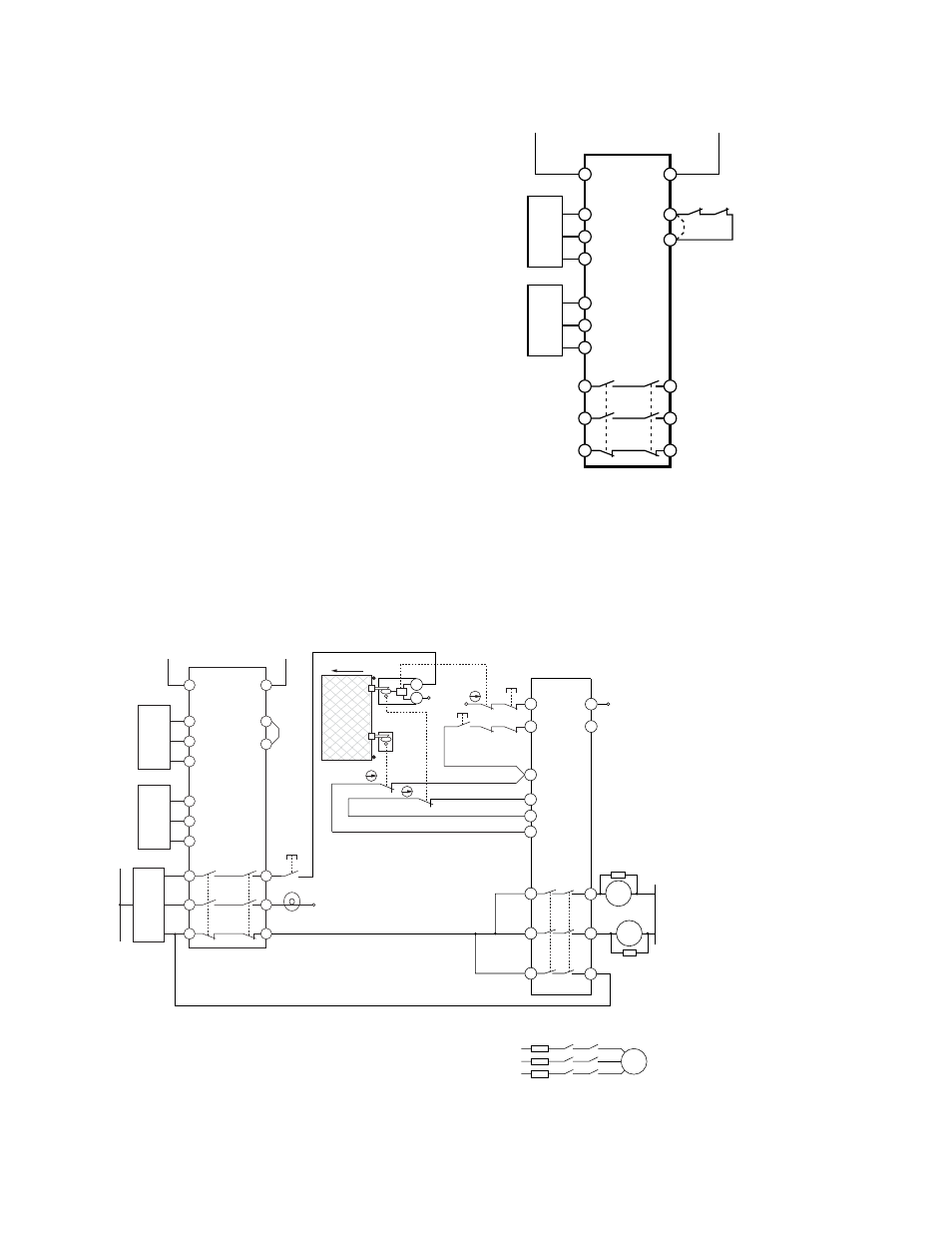
Figure 3. Typical hookup to two sensors
Connection to the Machine to be Controlled
The machine hookup diagram shows a generic connection of the Safety Module's redundant output circuits to the Machine Primary Con-
trol Elements MPCE1 and MPCE2. A Machine Primary Control Element is an electrically powered device, external to the Interface Mod-
ule, which stops the machinery being controlled by immediately removing electrical power from the machine and (when necessary) by
applying braking to dangerous motion.
0V
0V
n.c.
K1
A
K2
A
K1
B
K2
B
K1
C
K2
C
13
14
23
24
33
34
ES-FA-9AA
SSM-FM-11A10
or
SSM-FM-11A20
Sensor 2
24V ac/dc
0V
K1
A
4A max.
K2
A
K1
B
K2
B
K1
C
K2
C
Machine
Control
Circuits
Y1
Unlock (3)
OK to Open
+24V
0V
PNP
Signal
Out
13
S2+
S2s
S2-
Sensor 1
+24V
0V
PNP
Signal
Out
S1+
A2
A1
S1s
S1-
14
24
31
32
Y2
23
S12
S22
S21
24V ac/dc
Start
Function
(7)
A2
S34
OPEN
E1
E2
0V
0V
(5)
MPCE
1
MPCE
2
A1
S33
24V
ac/dc
(6)
MPCE1 MPCE2
Request to
Enter (2)
S11
Reset
(1)
M
MPCE1 MPCE2
(5)
(4)
Figure 4. Machine connection with an interlocked guard with guard locking and another safety module
NOTES:
SSM-FM-11A... Safe Speed Monitoring Modules
P/N 140782_web
rev. C
www.bannerengineering.com - tel: 763-544-3164
5