Banner Safe Speed Monitoring Modules User Manual
Page 14
2A / 230V ac for N.C. contact (per IEC/EN 60 947-5-1)
Electrical Life (Switching cycles of the output con-
tacts, resistive load)
350,000 cycles @ 920 VA
1,000,000 cycles @ 440 VA
2,000,000 cycles @ 250 VA
5,000,000 cycles @ 125 VA
Thermal Current Ith: 4A
Mechanical Life: More than 50,000,000 operations
Power Ranges
Min. voltage: 15V ac/dc
Max. voltage: 230V ac/dc
Min. current: 30 mA ac/dc
Max. current: 4 A
Min. power: 0.45 W (0.45 VA)
Max. power: 100 W (920 VA)
NOTE: Transient suppression is recommended when switching inductive loads. Install suppressor across load. Never install suppressor
across output contacts (see Warning).
Construction
Indicators
3 green LED indicators: Power On, Channel 1 active,
and Channel 2 active
Housing
Polycarbonate. Rated NEMA 1, IEC IP20 (IEC/EN 60
529)
Mounting
Mounts to standard 35 mm DIN rail track. Safety Mod-
ule must be installed inside an enclosure rated NEMA
3 (IEC IP54) or better.
Vibration Resistance
10 to 55 Hz @ 0.35 mm displacement per IEC
60068-2-6
Operating Conditions
Max. Rel. Humidity: 90% @ +50° C (non-condensing)
Temperature: 0° to 50° C (+32° to 122° F)
Design Standards
Cat. 3 PL e per DIN EN ISO 13849-1; SIL CL 3 per IEC
62061
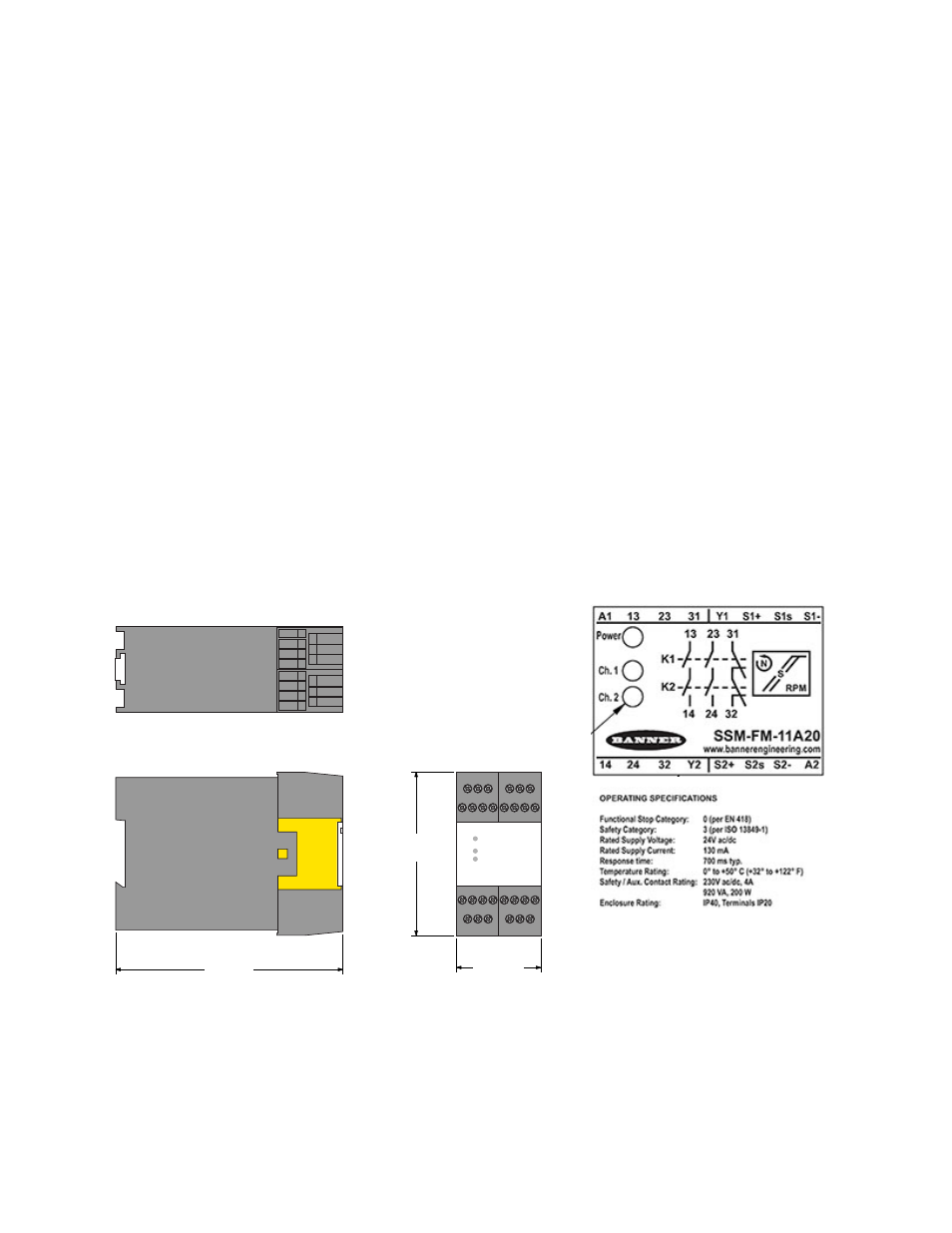
84 mm
(3.3")
45 mm
(1.8")
118.0 mm
(4.6")
Figure 10. Dimensions for SSM-FM-11A20
Certifications
Approvals are pending.
This module was evaluated by UL to UL508 Industrial Control Equipment, which is not a certification relating to the safety performance of
the module.
SSM-FM-11A... Safe Speed Monitoring Modules
14
www.bannerengineering.com - tel: 763-544-3164
P/N 140782_web
rev. C