Mechanical installation, Electrical installation, Figure 2. functional diagram – Banner Safe Speed Monitoring Modules User Manual
Page 4
Input Sensor Requirements
Both sensors must have 24V PNP outputs. Because the Module con-
tinually monitors its connections to each sensor, each sensor must
draw a minimum current of 3 mA at all times (in either the OFF or ON
state). The Module will detect if any of the three wires from the sen-
sor to the Module are interrupted. A broken sensor wire will always
result in an OFF condition.
• If the safety outputs are ON when a sensor wire breaks or is dis-
connected, the related internal relay turns OFF and the safety
outputs open, signaling "No Standstill" and/or "Over-speed."
• If the safety outputs are OFF when a sensor wire breaks or is dis-
connected, they can not turn ON (again signaling "No Standstill"
and/or "Over-speed") until the sensor connection is fixed.
Sensor Mounting Requirements: For safe and reliable operation,
the two input sensors must be mounted so that they are vibration-
free, their signals are received simultaneously, and they don't influ-
ence each other.
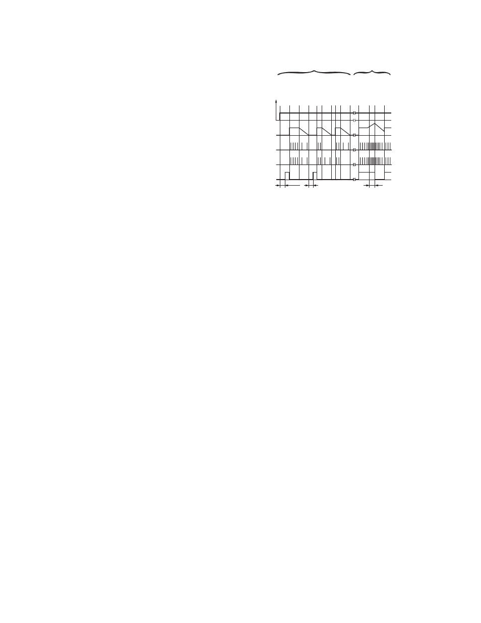
t
tds
Res +
Res
tds
tdo
13-14
23-24
Stop
Stop
Stop
Motor Standstill
Motor ON
Supply
ON
Standstill
Detection
Overspeed Detection
Motor ON
Overspeed
S1s
0V
A1/A2 +24V
S1s: Output signal from sensor A
Motor
Speed
S2s
Motor Standstill
Motor Standstill
Motor ON
Motor ON
Motor OFF
Motor ON
S2s: Output signal from sensor B
t : Power-up delay
detection
t : Response after overspeed detection
do
ds
t : Response after standstill/underspeed
Figure 2. Functional Diagram
Mechanical Installation
The Safety Module must be installed inside an enclosure.
It is not designed for exposed wiring. It is the user’s responsibility to house the Safety Module in an enclosure with NEMA 3 (IEC IP54)
rating, or better. The Safety Module mounts directly to standard 35 mm DIN rail; see Dimensions.
Heat Dissipation Considerations
For reliable operation, ensure that the operating specifications are not exceeded. The enclosure must provide adequate heat dissipation,
so that the air closely surrounding the Module does not exceed the maximum operating temperature stated in the Specifications. Methods
to reduce heat build-up include venting, forced airflow (e.g., exhaust fans), adequate enclosure exterior surface area, and spacing be-
tween modules and other sources of heat.
Electrical Installation
It is not possible to give exact wiring instructions for a Safety Module which interfaces to a multitude of machine control configurations.
The following guidelines are general in nature.
The Safety Module has no delay function. Its output relay contacts open within the time frame determined by the formula shown in the
Configuration section. This classifies the Safety Module as functional stop "Category 0", as defined by ANSI NFPA 79 and IEC/EN
60204-1.
Input Sensor Connections
The Module provides 24V dc and 0V to power the sensors through S1+/S1- and S2+/S2-. The sensor output signals are connected to
terminals S1s and S2s.
SSM-FM-11A... Safe Speed Monitoring Modules
4
www.bannerengineering.com - tel: 763-544-3164
P/N 140782_web
rev. C