Overview, Indicators, Operation and requirements – Banner Safe Speed Monitoring Modules User Manual
Page 3
Overview
The SSM-FM-11A.. Safe Speed Monitoring Module ("the Module") can be used to monitor a rotating or laterally moving device's stopping,
starting, or speed. The Module requires signals from two independent sensors.
As a "standstill" (under-speed) monitor, the Module is often used in combination with hard guarding, access doors, and safety gates with
solenoid-lock or -unlock safety switches. When the speed of the monitored device drops below the set switch point (where its speed is no
longer considered dangerous), the Module closes its safety output contacts, applying power to the safety switch solenoid, releasing the
switch lock and enabling the operator to open the safety gate.
In over-speed monitor applications, the N.O. safety contacts are closed for operation (when the motor speed of the monitored device is
below the set switch point). When the speed exceeds the set value, indicating a too-high (dangerous) speed, the safety output contacts
open.
Indicators
Standstill / Under-speed
Monitoring Applications
Over-speed Monitoring Ap-
plications
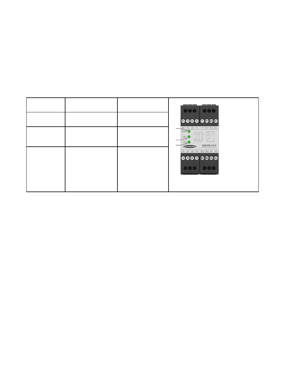
1
3
2
Figure 1. SSM-FM-11A... features and terminal
locations
1. Power ON (green)
when
Power is applied
Power is applied
2. Safety output
channel 1 ON
(green) when
Standstill signal detected on
Input Channel 1
No over-speed detected on
Input Channel 1
2. Safety output
channel 2 ON
(green ) when
Standstill signal detected on
Input Channel 2
No over-speed detected on
Input Channel 2
Operation and Requirements
The Module is redundant and self-checking. It requires digital input signals from two independent input sensors (e.g., proximity switches)
to monitor for either standstill (under-speed) or over-speed conditions.
The input channels are factory pre-adjusted for simultaneity, and a simultaneity potentiometer (behind the Module front cover) is available
to further synchronize the input channel timing. Two banks of DIP switches are also located behind the front cover, for the purpose of
selecting the switch point range; a second potentiometer is used to fine-tune the switch point setting. See Figure, "Module adjustments."
SSM-FM-11A... Safe Speed Monitoring Modules
P/N 140782_web
rev. C
www.bannerengineering.com - tel: 763-544-3164
3