Troubleshooting, Inputs and outputs, Switch power supply – Banner SureCross DX80 Wireless Networks User Manual
Page 81: Modbus register 8 message codes
81
Banner Engineering Corp. • Minneapolis, MN U.S.A.
www.bannerengineering.com • Tel: 763.544.3164
SureCross Wireless Network
Product Manual
Troubleshooting
Inputs and Outputs
Problem
Solution
Particular inputs and/or
outputs are not working
Use manual scrolling mode within *RUN to freeze the I/O status on the LCD display for the device in question. Verify
that when the input device changes state or changes value, the LCD mirrors the behavior.
Also verify that the LCD on the output side mirrors the linked input’s behavior. If the input device state LCD on
the origination DX80 and the LCD on the destination DX80 behave the same, there may be a wiring issue or an
interfacing problem. Consult the factory.
Nodes will not sample inputs unless they are in sync with a Gateway. Verify your Node is in sync with its Gateway.
Switch Power Supply
Problem
Solution
The sensor powered from
the Node’s switched supplies
does not get power.
There are several switched power outputs to power sensors (battery-powered devices only). Enable the power
supplies using the I/O point parameters for sensor supply #, supply output voltage, and warm-up time.
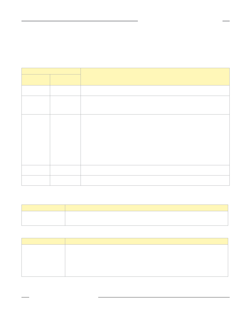
Modbus Register 8 Message Codes
Register I/O 8 is reserved for device messages or Site Survey data when in Site Survey mode (for more information about how Site Survey
data is stored in registers 7 and 8, refer to the Site Survey section). Conditions are detected as they occur and are immediately reported back
to the Gateway. Once the message is sent back to the Gateway, the Node does not resend the message until the condition changes or there is a
higher priority message. The higher the message code, the higher the priority.
The following are Modbus message codes, shown in hex, that may appear on the SureCross devices’ I/O 8 Modbus register.
0x0000 (Hex)
Definition
Message Code
[15:8]
Data Field
[7:0]
00
80
Normal operation. Device message register contents 0x0080 indicates the particular Node is synchronized
to the Gateway. (Decimal value 128.) A value of zero (0) indicates there is no device present.
01
00-FF
Unknown message. The message was received correctly (correct checksum), but it is not a recognized
command. This type of message is usually caused by devices with poor radio links or collocated networks
that are not uniquely separated by binding codes and Network IDs. This message does not affect the
performance of the network. (Decimal values 256 through 511.)
35
01
Radio Device Time-Out. (Decimal value 13569.) One of the Nodes is not responding to the Gateway’s
requests; the defined polling interval with allowable missed count was reached. See the documentation in
the UCT for polling or heartbeat parameters and the timeout operation. When the least significant bit is on
(1), an error condition exists.
• Run site survey to determine the quality of the RF link. If no communications exist between the Gateway
and Node, verify the power at the Node and all antenna connections. The blocking of RF communications
may also be a result of environmental conditions that may have changed.
• The battery of a battery powered Node may need to be replaced. Although the LCD and device may
appear functional, the battery may not have enough capacity to handle the current requirements of RF
communications.
36
01
Modbus time-out. A Gateway timeout (time of inactivity on the serial channel) was detected. (Decimal
value 13825.) When the least significant big is on (1), an error condition exists.
FE
-
Modbus register 8 device messages are disabled. The Modbus register 8 clears or disables message
using the Gateway’s Modbus register 15. (Decimal values 65024 through 65279.)