Rotary dial address mode, Step 3 - powering the node, Step 4 - verify communications, gateway and node – Banner SureCross DX80 Wireless Networks User Manual
Page 111: Step 5 - site survey, Line powered node pinout diagram, Gateway or gatewaypro, Node
111
Banner Engineering Corp. • Minneapolis, MN U.S.A.
www.bannerengineering.com • Tel: 763.544.3164
SureCross Wireless Network
Product Manual
Rotary Dial Address Mode
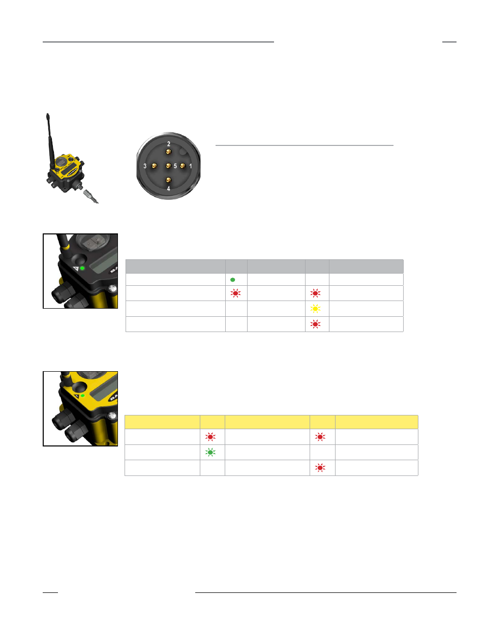
Line Powered Node Pinout Diagram
Wire No.
Color
Description
1
Brown
10–30V dc Input
3
Blue
dc common (GND)
Step 3 - Powering the Node
To apply power to the Node, connect the 10–30V dc cable or DX81 Battery Module as shown. As soon as power is applied to the Node, the
LCD displays POWER and begins cycling through the I/O points on the Node.
Step 4 - Verify Communications, Gateway and Node
Gateway or GatewayPro
Verify LED 1 is on and green. The image shown is a Gateway. The GatewayPro has no side glands.
Status
LED 1
LED 2
Power ON
Green ON
—
System Error
Red Flash
Red Flash
Modbus Communication Active
—
Yellow Flash
Modbus Communication Error
—
Red Flash
Node
Verify LED 1 is flashing green and LED 2 is off. Until communication is established with the Gateway, the Node’s
LED 2 flashes red. When communication is established, the Node’s LED 1 flashes green. Nodes will not sample
inputs unless they are in sync with a Gateway.
Status
LED 1
LED 2
System Error
Red Flash
Red Flash (1 per sec)
RF Link Ok
Green Flash (1 per sec)
—
RF Link Loss
—
Red Flash (1 per 3 sec)
If testing the Gateway or GatewayPro and Node before installation, verify the Gateway device and Node are at least two meters apart or the
communications may fail.
In a Gateway and Bridge system, Active Modbus communications refers to the communication between the Gateway and the Ethernet Bridge.
In a GatewayPro system, the Modbus communication LED refers to the communication internal to the GatewayPro. In a Gateway only system,
the Modbus communication LED refers to the communication between the Gateway and the host system.
Step 5 - Site Survey
Running Site Survey is optional. Site Survey analyzes the radio signal between a Gateway (or GatewayPro) and a specified Node, reporting
the number of data packets missed or received. To ensure reliable communication, perform the Site Survey before permanently installing your
network. Only the Gateway can perform a Site Survey analysis.
Refer to the Site Survey section for detailed instructions about how to conduct a Site Survey and how to interpret the results.