Troubleshooting, Lcd messages – Banner SureCross DX80 Wireless Networks User Manual
Page 80
80
Banner Engineering Corp. • Minneapolis, MN U.S.A.
www.bannerengineering.com • Tel: 763.544.3164
SureCross Wireless Network
Product Manual
Troubleshooting
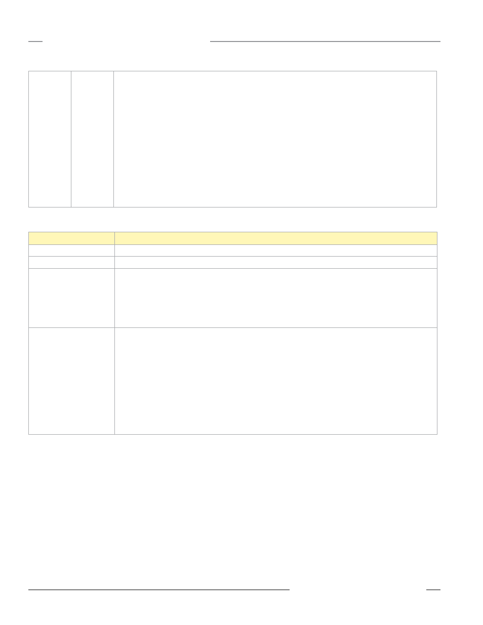
LCD Messages
Message
Definition
BAD EE
System Error. A system error typically represents a failure of the EE PROM. Contact the factory for replacement.
EC XX
The XX lists the Modbus register 8 message code listed in the Modbus Error Codes section of this table.
DX80 Display shows
*ERROR
The Gateway uses fully-acknowledged polling to ensure each Node RF link is robust. If a prescribed number of
sequential polling cycles are not acknowledged by a Node, the Gateway considers the radio link with that Node to be
timed out. All outputs on the Node in question are set to the user-selected default value or the output holds its last
state (as defined in the User Configuration Tool).
If the Node’s RF link recovers and the Gateway or GatewayPro determines enough acknowledged polling messages
have accumulated, the link is reinstated.
No LCD display
All DX80 devices display “POWER” on the LCD for the first five to ten seconds after applying power. A DX80
Gateway always has a green LED 1 on when power is connected. DX80 Node devices flash a red LED 2 every three
seconds or a green LED 1 every second depending on the RF Link status.
Battery-powered devices turn off the LCD after fifteen minutes (factory default). Push any button to reactivate the
LCD.
Battery-powered devices may be in power-down mode. To put battery powered devices into power-down mode, hold
button 1 for three to five seconds. To return from power-down mode, hold button 1 for three to five seconds.
Recheck the power connections and power requirements. Line-powered devices require 10 to 30V dc. Battery-
powered devices require 3.6 to 5.5V dc.
After replacing the battery, allow up to sixty seconds for the device to power up.
No LED 1
No LED 2
All DX80 devices display “POWER” on the LCD for the first five to ten seconds after applying power. A DX80
Gateway always has a green LED 1 on when power is connected. DX80 Node devices flash a red LED 2 every three
seconds or a green LED 1 every second depending on the RF Link status.
If no LEDs are lighting up:
1. Put battery powered devices into power-down mode using button 1 on the front panel. To put a battery device
into power-down mode, hold button 1 for three to five seconds. To return from power-down mode, hold button
1 for three to five seconds.
2. Recheck the power connections and power requirements. Line powered devices require 10 to 30V dc. Battery-
powered devices require 3.6 to 5.5V dc.
3. After replacing the battery, allow up to sixty seconds for the device to power up.
4. The GatewayPro cannot be attached to another Modbus master device or a Modbus slave ID 1 via RS485.
Special configuration using the Web page configuration tool allows the GatewayPro to become a slave unit
when necessary.