Units conversion in the banner wireless system, Units conversion – Banner SureCross DX80 Wireless Networks User Manual
Page 105
105
Banner Engineering Corp. • Minneapolis, MN U.S.A.
www.bannerengineering.com • Tel: 763.544.3164
Units Conversion
span to define the range. The null value is the starting temperature to be associated with 4 mA. The span is the entire temperature range that is
to be associated with 4 to 20 mA. For newer firmware models, type codes 8 and 9 are treated the same.
9. Signed Analog, 4 to 20 mA (B). In older models, this units type is for degree Fahrenheit conversions only. Use null to set the start point and
span to define the range. The null value is the starting temperature to be associated with 4 mA. The span is the entire temperature range that is
to be associated with 4 to 20 mA. For newer firmware models, type codes 8 and 9 are treated the same.
10. Unsigned Analog, 0 to 10V. For an unsigned value, such as 0 to 20 mA, that is to be converted to a voltage out value. Use the null to set
the start point and span to define the range. The null value is the distance to be associated with 0V. The span is the entire distance range that is
to be associated with 0 to 10V.
11. Counter, 16-bit. The 16-bit counter value records counts up to 65535.
12. Unsigned Analog, 4 to 20 mA. For an unsigned value, such as 0 to 10V, that is to be converted to a mA out value. Use the null to set the
start point and span to define the range. The null value is the distance to be associated with 4 mA. The span is the entire distance range that is
to be associated with 4 to 20 mA.
Units Conversion in the Banner Wireless System
The wireless devices have many different units of measure for inputs including: 0–20 mA, 4–20 mA, 0–10V dc, temperature (°C or °F),
humidity (RH), 32-bit value, or 16-bit value. Outputs can be either current (4–20 mA, 0–20 mA) or voltage (0–10V dc).
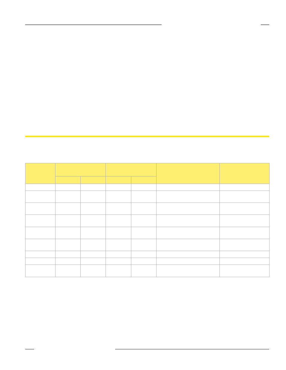
The following table defines the range of values and descriptions for input units. For temperature signed values, the register resolution is based
on the device configuration mode: in high resolution mode the register contains 0.1° and in low resolution mode the register contains 1°.
Input Type
I/O Range
Holding Register
Representation
Data Conversion
Description
Min. Value Max. Value Min. Value Max. Value
Discrete
0
1
0
1
-
0–20 mA
0.0 mA
20.0 mA
0
65535
(20mA
ч
65535) Ч Reg Value =
mA
Linear mapping of unsigned
register value to current
4–20 mA
4.0 mA
20.0 mA
0
65535
((16mA
ч
65535) Ч Reg Value) +
4 = mA
Linear mapping of unsigned
register value to current
0–10V dc
0.0V dc
10.0V dc
0
65535
(10V
ч
65535) Ч Reg Value = V
Linear mapping of unsigned
register value to voltage
Temp C/F (high
resolution)
-1638.3
+1638.4
-32768
32767
(Reg Value) ÷ 20 = Temp
Signed Values
Temp C/F (low
resolution)
−16383°
+16384
-32768
32767
(Reg Value) ÷ 2 = Temp
Signed Values
Counter
0
65535
0
65535
-
-
16-bit T30U
0 mm
65535 mm
0
65535
None; stored as millimeter value
Unsigned
Humidity
0% RH
100% RH
0
10000
(Reg Value) ÷ 100 = Relative
Humidity (RH)
Unsigned
* 0.01 ma A/D resolution, 0.02 mA accuracy + 0.01% per degrees C (about 0.08 mA over ± 40 degrees)
Temperature Measurements: In high resolution mode, the temperature = (Modbus register value)÷20. For high resolution temperature input, 0 in the register is interpreted as 0°
and 65535 in the register (0xFFFF) is interpreted as −1 ÷ 20 = −0.05°.
In low resolution mode, the temperature is (Modbus register value)÷2. For low resolution temperature input, 0 in the register is interpreted as 0° and 65535 in the register
(0xFFFF) is interpreted as −1 ч 2 = −0.5°.