Menu structure, Introduction, Dx80 gateway and gatewaypro setup menu – Banner SureCross DX80 Wireless Networks User Manual
Page 13: Surecross wireless network, Product manual, Dinfo, Fctry, Site, Dvcfg, Derr
13
Banner Engineering Corp. • Minneapolis, MN U.S.A.
www.bannerengineering.com • Tel: 763.544.3164
SureCross Wireless Network
Product Manual
Introduction
Menu Structure
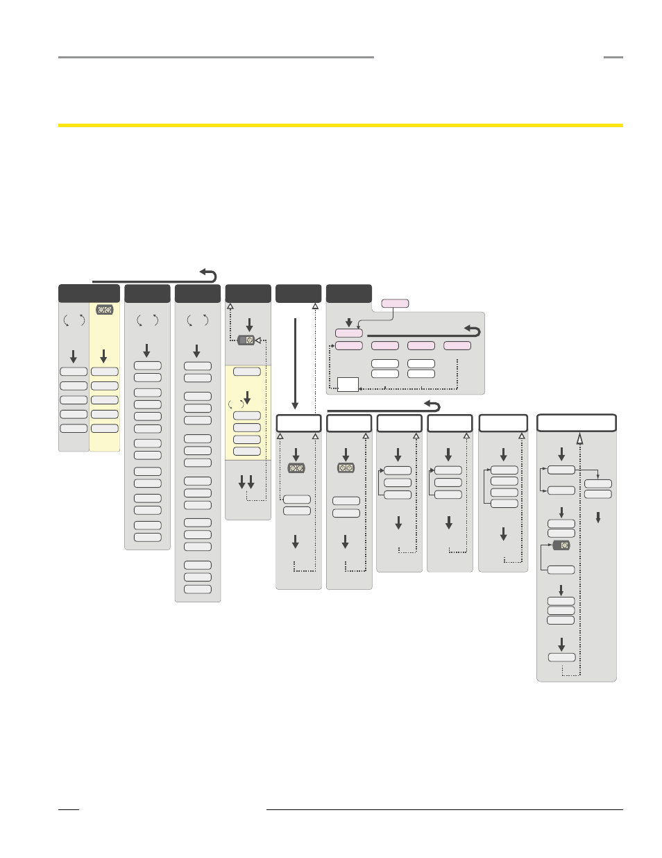
DX80 Gateway and GatewayPro Setup Menu
When power is applied, the DX80 begins running. The display screen auto loops through the RUN menu and communication begins between
the Gateway and Node(s). Auto looping through the RUN menu is the normal operating mode for all devices on the wireless network.
From the RUN Menu (or any menu), single-click button 1 to advance through the top-level menus. The device auto display loops through the
menu options if either of the RUN, DINFO, or FCTRY menus are selected. If the device is paused on the SITE, DVCFG, or DERR menu options,
the display does not auto loop.
To enter manual scrolling mode, double-click button 2 at the top level menu. Use the instructions shown in the chart below to navigate the
menu system. To return to the top level menus and auto display loop mode, double-click button 2 twice.
NOD XX
M XX
R XX
Y XX
G XX
*
DINFO
*
FCTRY
*
SITE
*
DVCFG
*
DERR
*
RUN
AUTO
DISPLAY
LOOP
AUTO
DISPLAY
LOOP
AUTO
DISPLAY
LOOP
(DEV)
GATEWY
(NID)
XX
(SLID)
XX
(BAUD)
XX
(PRTY)
XX
(DEV)
GATEWY
(RADIO
MICRO)
V 00.0 A
(LCD
MICRO)
V 00.0 A
(DX80
S/N)
(0000)
(DX80
MODEL)
(0000-00)
(PROD
DATE)
(00-00)
Single-click
Button 2
Single-click
Button 2
Single-click
Button 2
Double-click
Button 2
adjust right rotary
switch to survey the
selected Node
Single-click
Button 2
Double-click
Button 2
Double-click Button 2
NOD XX
EC XX
CLEAR
ERR
ERASED
ERR
DISABL
*
ERROR
DISABL
IGNORE
Next
Device
Single-click Button 1 to advance through menu
AUTO
DISPLAY
LOOP
Single-click
Button 2
Single-click
Button 2
Single-click
Button 2
Single-click
Button 2
Single-click
Button 2
Single-click
Button 2
New Error
Detected
adjust the rotary
switches to survey
the selected Node
(DEV)
I/O XX
GATEWY
NID XX
ON/OFF
(DEV)
I/O XX
GATEWY
NID XX
ON/OFF
Even
None
Odd
Single-click
Button 2
Single-click
Button 2
SAVES
DISPLAYED
VALUE
Single-click B1
19200
9600
38400
Single-click
Button 2
Single-click
Button 2
SAVES
DISPLAYED
VALUE
NEW XX
Single-click
Button 2
Single-click
Button 2
adjust rotary switches
to set the network ID
SAVES NEW
VALUES
CUR XX
Single-click
Button 2
Single-click
Button 2
adjust rotary switches
to set slave ID, using
button 1 to select the
digits
SAVES NEW
VALUES
(NID)
(SLID)
(BAUD)
(PRTY)
Network ID
Slave ID
Baud Rate
Parity
Single-click B1
NEW XX
Single-click
Button 1
Single-click
Button 1
Single-click
Button 1
Single-click
Button 1
Single-click Button 1 to advance through menu
(NAME)
XXXXXX
XXXXXX
Single-click Button 1 to advance through menu
CUR XX
Double-click Button 2
Double-click
Button 2
* Set to 000000 to use the serial number.
Device Info
Factory Info
Site Survey
Device Config
Device Error
16
8
32
Single-click
Button 2
Single-click
Button 2
SAVES
DISPLAYED
VALUE
Single-click B1
(MAXN)
Timing
48
MANUAL
AUTO
AUTO
SET
Single-click
Button 2
Single-click
Button 2
Single-click B1
(XADR)
Extended Addressing
XADR
ADJUST ROTARY
SWITCH TO
SET XADR
Single-click
Button 2
XXXXXX
Single-click B1
Single-click
Button 2
CONFRM
XADR
XXXXX
NETWRK
Single-click
Button 2
BINDNG
Single-click
Button 1 or 2
Reboot
SAVED
*
XXXXXX
The Network ID (NID) can be set at any time using the rotary
switches. Once changed, allow five seconds for the devices to update
to the new NID.
Navigating the menu:
* indicates a top level menu option
( ) indicates a sub-menu item
No characters indicate the value of the previous item
The MAXN and XADR menus are only available in extended addressing mode. To access extended addressing mode, move DIP switch 1 to the
ON position. To manually select the serial number, use button 1 to move across the digits and use the right rotary switch to select the value
used as the device serial number.