Periodic checkout procedures, 1 schedule of checkouts, 2 trip test – Banner EZ-SCREEN Safety Light Curtain Systems User Manual
Page 50
48
P/N 68413 rev. A
Banner Engineering Corp.
•
Minneapolis, U.S.A.
www.bannerengineering.com • Tel: 763.544.3164
EZ-SCREEN Point
Instruction Manual
Periodic Checkout Procedures
Study each procedure from beginning to end before you
start to make sure that you understand each step. Refer all
questions to the Banner Applications Engineering Department at
the address or numbers listed on the front cover of this manual.
Checkouts must be performed as detailed in Section 6.1 below
and results should be recorded and kept in the appropriate
place (e.g., near the machine, and/or in a technical file).
NOTE: If multiple EZ-SCREEN Point Systems are combined
to form a light grid, each individual System must be
tested.
6.1 Schedule of Checkouts
Initial Checkout: The procedure for initial checkout of the
EZ-SCREEN Point System is described in Section 3.6. This
procedure is performed at installation, and at any time the
System, the guarded machine, or any part of the application
is installed or altered . The procedure must be performed by a
Qualified Person.
Commissioning Checkout: Should be performed at installation
or whenever changes are made to the system (either a new
configuration of the EZ-SCREEN System or changes to the
machine). The procedure must be performed by a Qualified
Person .
Daily Checkout: The procedure for “daily” checkout of the EZ-
SCREEN Point System is to be performed at each shift change
or machine setup change, whenever the System is powered up,
at least daily. The procedure may be performed by a Designated
Person or a Qualified Person.
Semi-Annual Checkout: The procedure for initial checkout of
the EZ-SCREEN Point System is to be performed at every six
months, following installation of the System. The procedure
must be performed by a Qualified Person.
6. Periodic Checkout Procedures
6.2 Trip Test
Once the Beam Status indicator is steady Green, trip test the
EZ-SCREEN System to verify proper operation and to detect
possible reflection problems, using the test piece included with
the System. With power ON:
1. Verify that the EZ-SCREEN Point System is in Run mode;
receiver status indicators should be as follows:
Status indicator
Green
Beam Status indicator Green
Reset indicator
ON
Diagnostic Display
“–” (Trip Output mode) or
“L” (Latch Output mode)
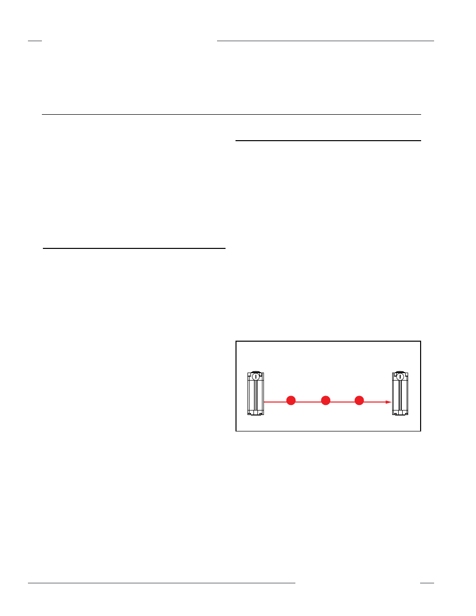
2. Pass the test piece downward through the beam at three
points: near the receiver, near the emitter, and midway
between them. In each case, verify that the Beam Status
indicator on the receiver turns steady Red and remains steady
Red while the test piece is blocking the beam. Also, verify that
the Status indicator is steady Red while the beam is blocked.
If the emitter and receiver are far apart, a second person may
be needed to monitor the indicators while the test piece is
used near the emitter or in the midway position.
Emitter
Test Piece
Receiver
Figure 6-1. EZ-SCREEN Point trip test