Components and specifications, Ez-screen point, Instruction manual – Banner EZ-SCREEN Safety Light Curtain Systems User Manual
Page 16
14
P/N 68413 rev. A
Banner Engineering Corp.
•
Minneapolis, U.S.A.
www.bannerengineering.com • Tel: 763.544.3164
EZ-SCREEN Point
Instruction Manual
Components and Specifications
BEAM
1
R
E
S
E
T
S
T
A
T
U
S
BEAM
1
R
E
S
E
T
S
T
A
T
U
S
EZ-SCREEN Point
BANNER ENGINEERING CORP., USA
888.373.6767
EZ-SCREEN Point
BANNER ENGINEERING CORP., USA
888.373.6767
See Notes
Below
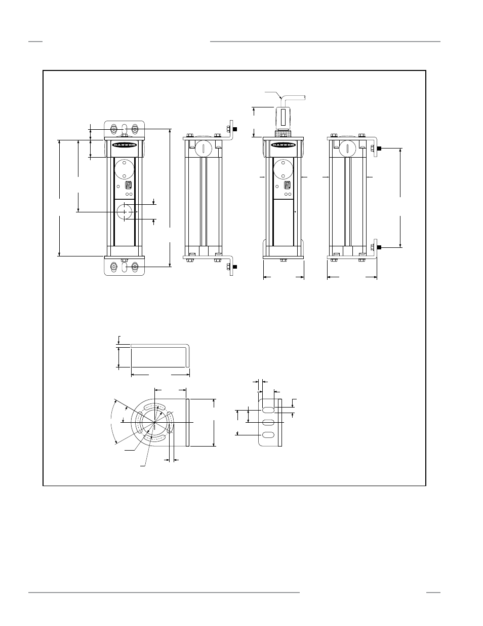
12.5 mm (0.50")
Minimum Bend Radius
107.0 mm
(4.21")
26 mm
(1.02")
149 mm
(5.9")
182 mm
(7.2")
60.0 mm
(2.36")
74.2 mm
(2.92")
124 mm
(4.9")
16.7 mm
(0.66")
52 mm
(2.0")
55 mm
(2.1")
25 mm
(1.0")
Figure 2-1. EZ-SCREEN Point dimensions (standard end-cap brackets shown) and EZA-MBK-1 mounting bracket dimensions
EZ-SCREEN
Standard Mounting Bracket
EZA-MBK-1
74.2 mm
(2.92")
4.2 mm
(0.17")
25.0 mm
(0.98")
60.0 mm
(2.36")
40 mm
(1.57")
ø 32.0 mm
(1.26")
ø 43.0 mm
(1.69")
2x 30.0°
2x 60.0°
4x 5.8 mm
(0.23")
5.0 mm
(0.20")
15.0 mm
(0.59")
3x 7.0 mm
(0.28")
15.8 mm
(0.62")
31.5 mm
(1.24")
CL
CL
See page 11 for information
about other accessory brackets .
NOTE: QD models have identical mounting dimensions.
Allow additional height for QD fitting:
69 mm (2.7” for emitters (3- or 5-pin)
89 mm (3.5”) for receivers (8-pin)