System installation, 5 adjacent reflective surfaces, Warning – Banner EZ-SCREEN Safety Light Curtain Systems User Manual
Page 24: Caution
22
P/N 68413 rev. A
Banner Engineering Corp.
•
Minneapolis, U.S.A.
www.bannerengineering.com • Tel: 763.544.3164
EZ-SCREEN Point
Instruction Manual
System Installation
3.3.5 Adjacent Reflective Surfaces
A reflective surface located adjacent to the light beam(s) may
deflect light around an object in the beam(s). In the worst case,
such a situation may allow an object to pass undetected through
the beam(s).
This reflective surface may result from shiny surfaces or glossy
paint on the machine, the workpiece, the floor or the walls.
Beams deflected by reflective surfaces are discovered by
performing the trip test portion of the final alignment procedure
and the periodic checkout procedures (Sections 3.6 and 6). To
eliminate problem reflections:
• If possible, relocate the sensors to move the beam away
from the reflective surface(s), being careful to maintain
adequate separation distance .
• Otherwise, if possible, paint, mask or roughen the shiny
surface to reduce its reflectivity.
• Where these are not possible (as with a shiny workpiece),
include a means of restricting the receiver’s field of view or
the emitter’s spread of light in the sensor mounting .
• Repeat the trip test to verify that these changes have
eliminated the problem reflection(s). If the workpiece is
especially reflective and comes close to the light beam(s),
perform the trip test with the workpiece in place.
WARNING . . .
Avoid Installation Near
Reflective Surfaces
Avoid mounting the EZ-SCREEN Point near
any reflective surfaces. A reflective surface located nearby
may reflect light around an object or person, preventing its
detection by the receiver. This possibility is detected during
the trip test.
Failure to prevent reflection problems will result in incomplete
guarding; serious bodily injury or death could result.
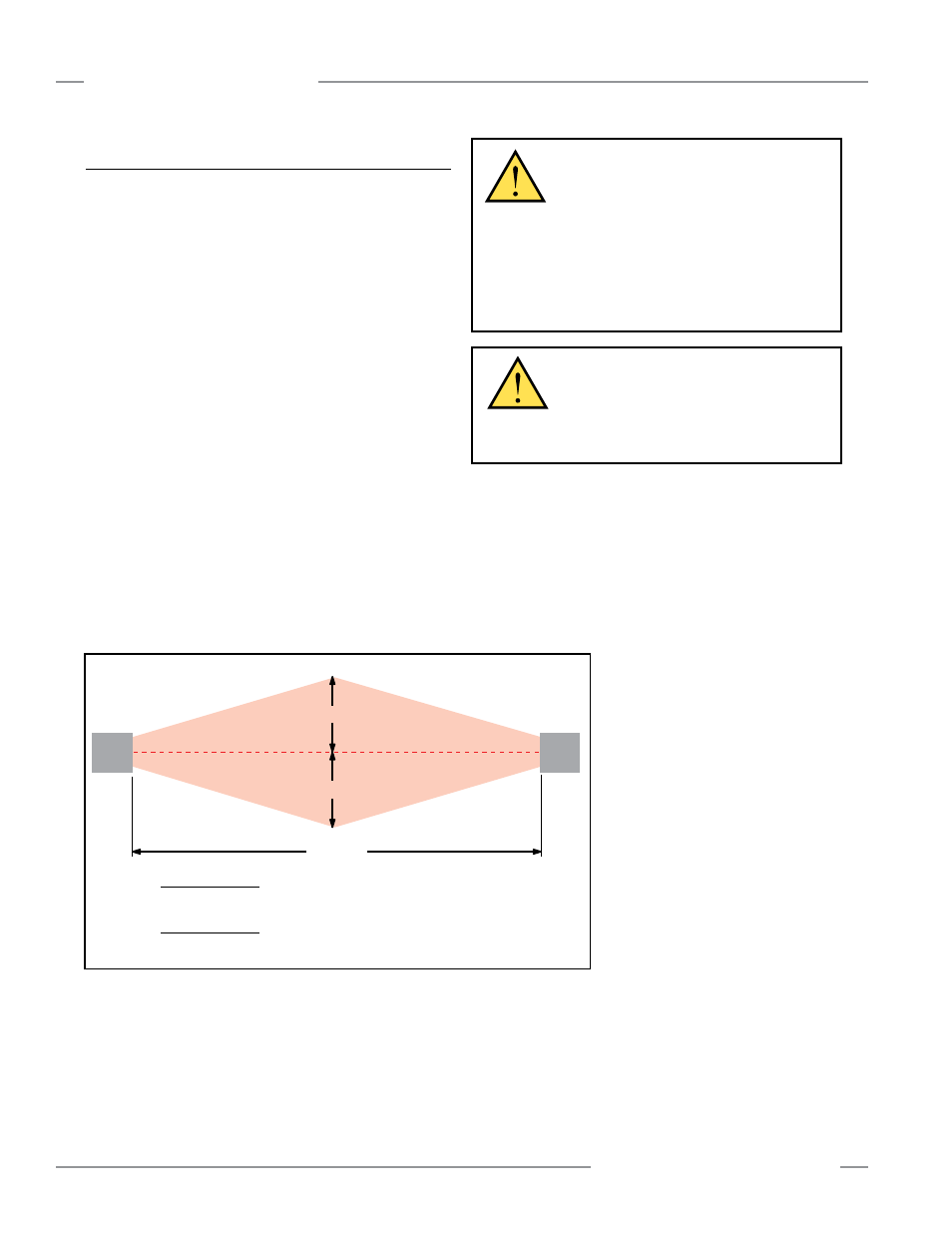
Emitter
Receiver
Operating
Range (R)
d
d
Do not position
reflective surfaces
within the shaded area
Short-Range Models
Operating Range 0.8 to 3 meters (2.6' to 10'): d = 131 mm (5.2')
Operating Range 3 to 20 meters (10' to 65'): d = 0.0437 x R (meters or feet)
Long-Range Models
Operating Range 15 to 70 meters (49' to 230'): d = 0.0437 x R (meters or feet)
Figure 3-9. Adjacent reflective surfaces
CAUTION . . .
Proper Model Selection
Ensure proper selection of emitter models, with
respect to range (operating distance) between emitter
and receiver, to minimize the possibility of optical short circuits (see
Sections 2.1 and 3.3.4).