System installation – Banner EZ-SCREEN Safety Light Curtain Systems User Manual
Page 32
30
P/N 68413 rev. A
Banner Engineering Corp.
•
Minneapolis, U.S.A.
www.bannerengineering.com • Tel: 763.544.3164
EZ-SCREEN Point
Instruction Manual
System Installation
Optical Alignment Procedure
After the emitter and receiver are mechanically aligned
(perpendicular to the floor along the path of the beams, and plumb in
all possible directions), optically align them, first using the LAT-1, if
desired, and finally using the receiver Beam Status indicator.
Using the LAT-1 for Alignment
The LAT-1 Laser Alignment Tool (see Section 2.2) is extremely
helpful for initial optical alignment, especially in long-range
applications and when corner mirrors are used.
The useable range of the LAT-1 (the red dot viewed at the target)
depends on the color and reflectance of the target, the level of
ambient light present, and the presence of airborne contaminants.
With a 90 percent reflectance white test card, under average lighting
and with no airborne contaminants, the red dot is viewable at
approximately 150' or more. For longer ranges, the lighting should be
dimmed or retroreflective targets should be used. The optional clip-
on retroreflective target (EZA-LAT-1) can increase the target area
and the visibility of the red dot created by the laser beam (see Figure
3-17).
Figure 3-15. The LAT-1 Laser Alignment Tool, in position on
the emitter beam
Beam location mark
is visible in center
of hole
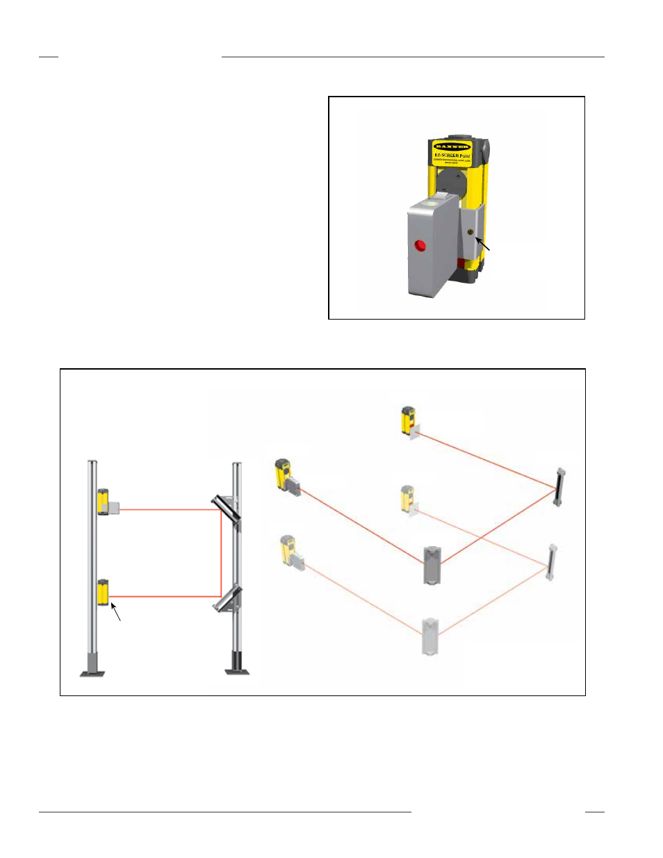
Figure 3-16. Optical alignment using the LAT-1
Emitter
Emitter
Mirror #1
Mirror #2
Receiver
Receiver
Retroreflective
Tape
When multiple EZ-SCREEN
Systems are used together,
each system should be aligned
separately.
LAT-1
Emitter
LAT-1
Retroreflective
Tape
Receiver