3 supported modbus function codes – Banner SureCross DX80 Wireless Networks User Manual
Page 7
In this format, users can read a 16-bit holding register for all devices or write to a register for all devices using one
Modbus message. Using these registers is the most efficient way to read all status registers, read all analog inputs, or
write all analog outputs.
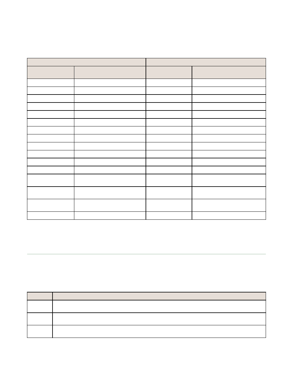
The following registers contain analog I/O values for the Gateway and all Nodes. Values are stored first for the Gateway,
then for each Node in order of Node address.
Inputs
Outputs
Modbus Register
Address (Decimal)
Description (Inputs)
Modbus Register
Address (Decimal)
Description (Outputs)
6801
Input 1 for Gateway
8001
Output 1 for Gateway
6802
Input 1 for Node 1
8002
Output 1 for Node 1
6803
Input 1 for Node 2
8003
Output 1 for Node 2
...
...
...
...
6951
Input 2 for Gateway
8151
Output 2 for Gateway
6952
Input 2 for Node 1
8152
Output 2 for Node 1
6953
Input 2 for Node 2
8153
Output 2 for Node 2
...
...
...
...
7101
Input 3 for Gateway
8301
Output 3 for Gateway
7102
Input 3 for Node 1
8302
Output 3 for Node 1
7103
Input 3 for Node 2
8303
Output 3 for Node 2
...
...
...
...
7851
Input 8 (Status Register) for
Gateway
9051
Output 8 for Gateway
7852
Input 8 (Status Register) for Node
1
9052
Output 8 for Node 1
7853
Input 8 (Status Register) for Node
2
9053
Output 8 for Node 2
...
...
...
...
For example, 6801 contains the input 1 value for the Gateway, 6802 contains the input 1 value for Node 1, and 6848
contains the input 1 value for Node 47.
2.3 Supported Modbus Function Codes
The supported Modbus function codes are 3 (read multiple), 6 (write single), and 16 (write multiple).
All DX80 Modbus registers are defined as ‘holding registers’ in the 4xxxx address space. Some older PLCs use the register
number space of 4xxxx to imply function code 3 for holding registers. For these systems, add 40000 to our register
number and the PLC software uses the correct function code 3 to access our registers.
.
Function
Description
3
Reads the contents of a contiguous block of holding registers in a remote device. The request specifies the
starting register address and the number of registers.
6
Writes a single holding register in a remote device. The request specifies the address of the register to be
written and the single register of data.
16
Writes a block of contiguous holding registers in a remote device. The requested written values are specified
in the request data field.
Host Controller Systems
7