4 conducting a site survey using modbus commands – Banner SureCross DX80 Wireless Networks User Manual
Page 32
There are 16 Modbus holding registers for each SureCross device. To calculate the registers for other Nodes, use this
equation: Register number = I/O# + (Node # × 16). For example, the Gateway is always device 0 (or Node 0), so the
Gateway’s holding registers are registers 1 through 16. The registers for Node 1 are 17 through 32 and the registers for
Node 2 are 33 through 48.
Node Reg 16
Low or High Value
Node Reg 15
143 or 144 (0x8F or 0x90)
Counter Select Mask
Node Reg 7
Acknowledge Code 143 or 144
Acknowledge Counter Select Mask
Example: To preset Node 2’s counter 2 to the value 20,567,001 (hex 0139 D3D9), follow these steps:
1. Write the upper word to the counter using control code 144 (0x90).
Node Reg 48
0139
Node Reg 47
0x90
2
Node Reg 39
0x90
2
2. Write the lower word to the counter using control code 143 (0x8F).
Node Reg 48
D3D9
Node Reg 47
0x8F
2
Node Reg 39
0x8F
2
The counter has been preset to 20,567,001 (0x0139 D3D9)
7.4 Conducting a Site Survey Using Modbus Commands
A Site Survey can be started using Modbus commands sent from the host system.
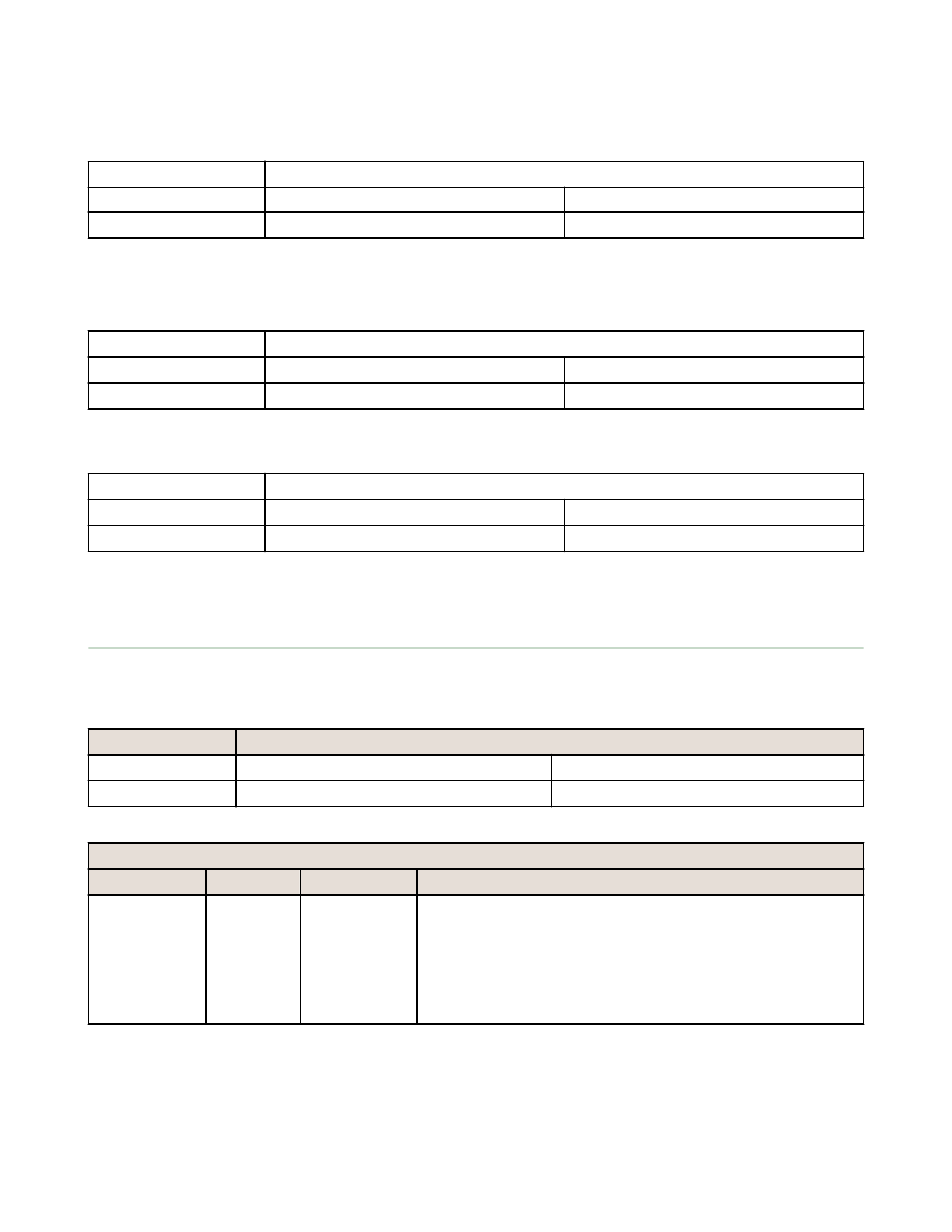
To start a Site Survey using a Modbus write holding register command, send a control code of 32 (0x20) and the Node
number 1–15 (0x01 to 0x0F) to the Gateway Modbus holding register for I/O 15.
Modbus Register
[15:8]
[7:0]
I/O 15
Control Code
Data Field
I/O 15 Control Messages
Control Code
Data Field
Restrictions
Description
32
Node # 1-15 Gateway only
Enable Site Survey between Gateway and Node defined by the data
field. All error messages from the Gateway are ignored when running
Site Survey.
Only one Node can participate in Site Survey at any given time. To
disable the Site Survey, use control code 0x20 with Node 0. A Node
must be enabled to run the Site Survey, then disabled before
selecting the next Node.
Host Controller Systems
32