2 parameter definitions and numbers – Banner SureCross DX80 Wireless Networks User Manual
Page 23
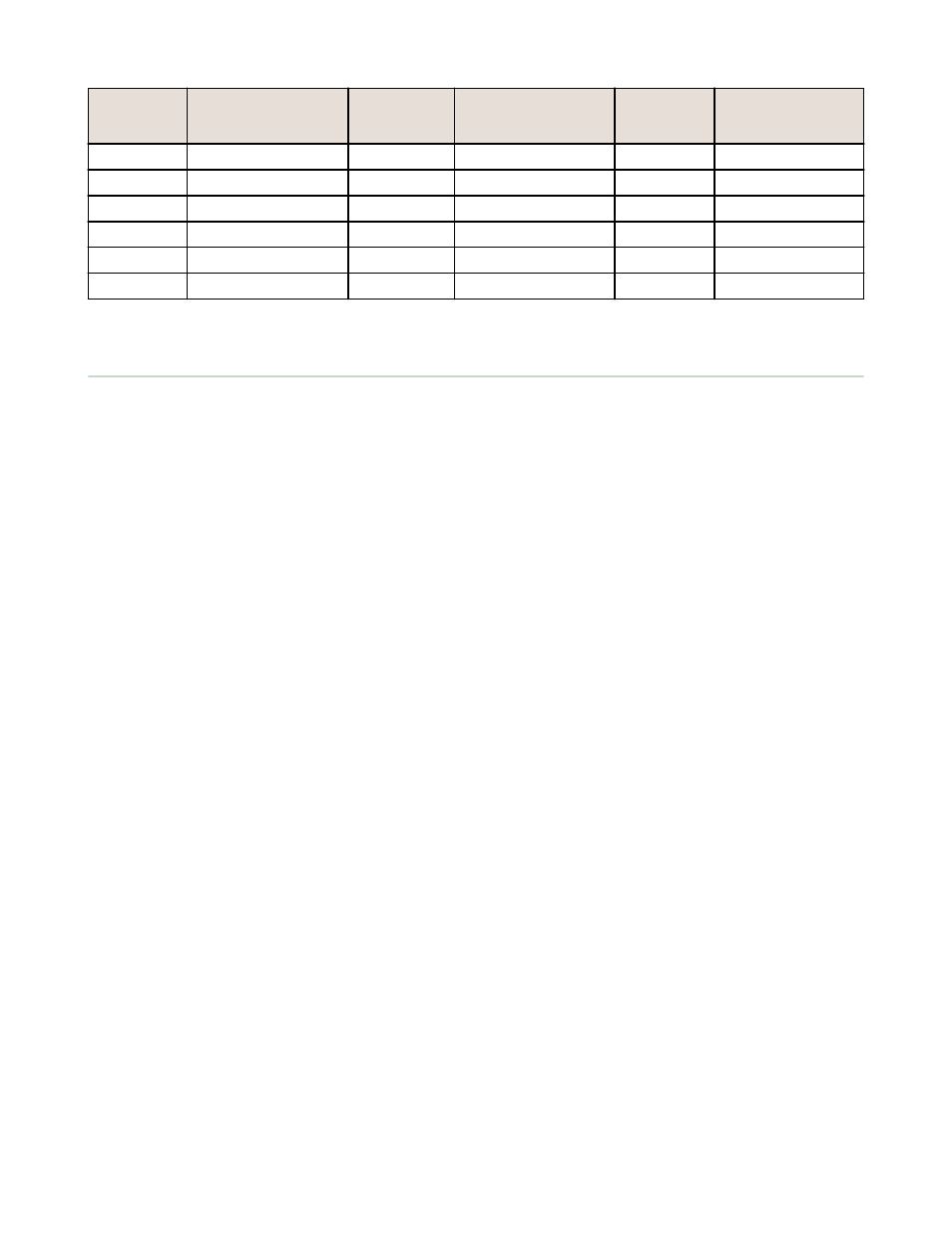
Extended
Control
Code (Dec)
Description
Extended
Control Code
(Dec)
Description
Extended
Control
Code (Dec)
Description
0x89 (137)
Write I/O 9
0xA9 (169)
Read I/O 9
0xAF (175)
Reserved
0x8A (138)
Write I/O 10
0xAA (170)
Read I/O 10
0xB0 (176)
Reserved
0x8B (139)
Write I/O 11
0xAB (171)
Read I/O 11
0x8C (140)
Write I/O 12
0xAC (172)
Read I/O 12
0x8D (141)
Write I/O 13
0xAD (173)
Read I/O 13
0x8E (142)
Write I/O 14
0xAE (174)
Read I/O 14
6.2 Parameter Definitions and Numbers
The following parameters can be changed using the User Configuration Tool or by sending register commands from your
host system.
Counter Enable. An enable byte that turns any input point into a synchronous counter. Set to 0 to turn off (default). Set
to 1 to enable the 16-bit counter (report type must be set to analog). Set to 2 to enable the 32-bit counter (report type
must be set to double). (Parameter number 0x18). The counter value is stored in the Modbus registers. For a 32-bit
counter type, Modbus registers N and N+1 are used.
Default Value (bits 15:0). Defines the default state for each output on all devices. This parameter only applies to
outputs. A value of 65535, or 0xFFFF, sets the default value to the last known state. (Parameter number 0x11). There are
five conditions that cause the output points to be set:
•
Bit 1. Power-up. If enabled, output points are set to the default state when the device powers up. When disabled,
outputs are set to 0 when the device powers up.
•
Bit 2. Node Out-of-Sync. If enabled, the output points are set to the default state when a Node determines it is out
of sync with the Gateway (7 to 10 sec). When disabled, no action takes place for the output points when an out-of-
sync condition is detected.
•
Bit 3. Host Link Failure. A Modbus user-defined timeout period expired. If enabled, a host link failure forces all
device outputs to the user-defined default state. Each device can be enabled/disabled for this feature.
•
Bit 4. Gateway Link Failure. The Gateway has detected a problem with a Node in the system. If enabled, any Node
outputs linked to the failing device are set to the default state when a Gateway link failure is detected. Each device
can be enabled or disabled to use this feature.
•
Bit 5. Node Link Failure. The Node detected a problem communicating with the Gateway. If enabled, the Node sets
all outputs to the user-defined default state when a Node link failure is detected. Each device can be enabled or
disabled to used this feature.
Delta (bits 15:0). Defines the amount of change required between two successive analog input sample points to trigger a
report condition. To disable (default), set to 0. (Parameter number 0x0F).
Duty Cycle (Outputs only) (bits 15:0). This parameter defines the proportion of time the output is active. Using the
16-bit field, each “on” bit represents 1/16 seconds. For example, 0000 0000 0000 1111 (0x000F) sets the duty cycle to
1/4 seconds; 0000 0000 0000 0011 (0x0003) sets the duty cycle to 1/8 seconds. (Parameter number 0x04).
Enable Flag (bit 0). Enables (1) or disables (0, default) the I/O point. (Parameter number 0x01).
Hysteresis (bits 15:0). Works with the active threshold parameter to define when to disable event reporting of an analog
input. The hysteresis parameter defines how much below the active threshold the analog input is required to be before the
analog input is considered to be off. Value range: 0 (disable, default) through 65535 (two-byte value). (Parameter number
0x09).
I/O Config. The I/O Config parameter is a configuration parameter for smart sensor devices. This parameter also defines
I/O information for the Extended Logic I/O type. (Parameter number 0x14).
I/O Type (bits 7:0). Defines the operations required to operate this I/O point. Every enabled I/O point must have a
defined I/O type. (Parameter number 0x02). This parameter is hardware specific and is not typically changed from the
factory settings. (See input and output type tables after this section.)
Invert Flag (bit 0). Complements the polarity of the sensed I/O point. A value of 1 becomes 0. An analog value is not
changed, but an analog value with a threshold and hysteresis is complemented. Value range: 0 (inactive) to 1 (active).
(Parameter number 0x10).
Host Controller Systems
23