Banner SureCross DX80 Wireless Networks User Manual
Page 6
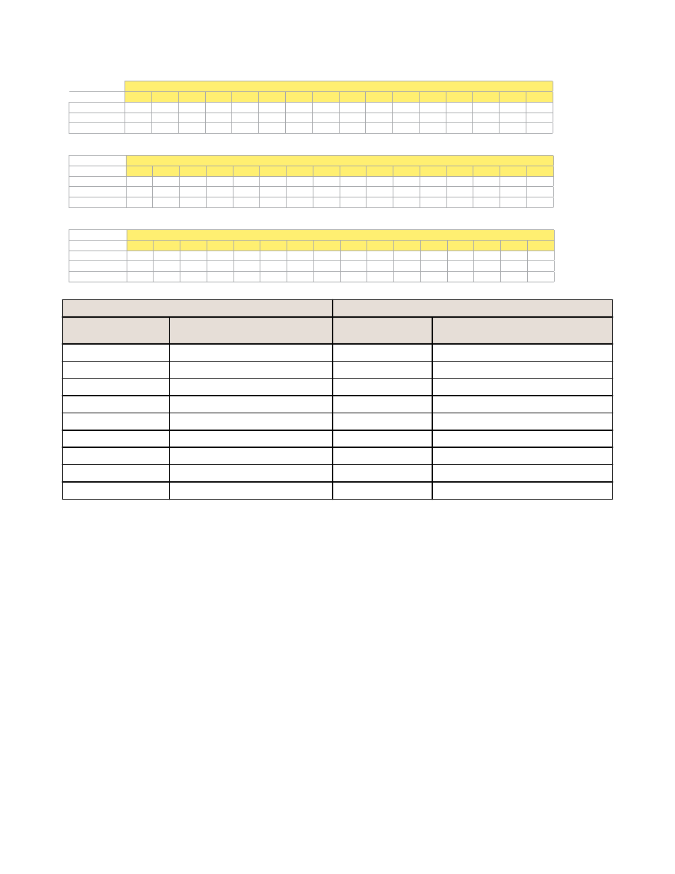
Bit-Packed Device Status Registers
Bit Position
Register Address
15
14
13
12
11
10
9
8
7
6
5
4
3
2
1
0
6601
Node 15 Node 14 Node 13 Node 12 Node 11
Node 10
Node 9
Node 8
Node 7
Node 6
Node 5
Node 4
Node 3
Node 2
Node 1
Gateway
6602
Node 31 Node 30 Node 29 Node 28 Node 27 Node 26 Node 25 Node 24 Node 23 Node 22 Node 21 Node 20 Node 19 Node 18 Node 17 Node 16
6603
Node 47 Node 46 Node 45 Node 44 Node 43 Node 42 Node 41 Node 40 Node 39 Node 38 Node 37 Node 36 Node 35 Node 34 Node 33 Node 32
Bit-Packed Discrete Input 1
Bit Position
Register Address
15
14
13
12
11
10
9
8
7
6
5
4
3
2
1
0
6611
Node 15 Node 14 Node 13 Node 12 Node 11
Node 10
Node 9
Node 8
Node 7
Node 6
Node 5
Node 4
Node 3
Node 2
Node 1
Gateway
6612
Node 31 Node 30 Node 29 Node 28 Node 27 Node 26 Node 25 Node 24 Node 23 Node 22 Node 21 Node 20 Node 19 Node 18 Node 17 Node 16
6613
Node 47 Node 46 Node 45 Node 44 Node 43 Node 42 Node 41 Node 40 Node 39 Node 38 Node 37 Node 36 Node 35 Node 34 Node 33 Node 32
Bit-Packed Discrete Output 1
Bit Position
Register Address
15
14
13
12
11
10
9
8
7
6
5
4
3
2
1
0
6691
Node 15 Node 14 Node 13 Node 12 Node 11
Node 10
Node 9
Node 8
Node 7
Node 6
Node 5
Node 4
Node 3
Node 2
Node 1
Gateway
6692
Node 31 Node 30 Node 29 Node 28 Node 27 Node 26 Node 25 Node 24 Node 23 Node 22 Node 21 Node 20 Node 19 Node 18 Node 17 Node 16
6693
Node 47 Node 46 Node 45 Node 44 Node 43 Node 42 Node 41 Node 40 Node 39 Node 38 Node 37 Node 36 Node 35 Node 34 Node 33 Node 32
Inputs
Outputs
Modbus Register
Address (Decimal)
Description (Inputs)
Modbus Register
Address (Decimal)
Description (Outputs)
6601-6603
Status for all devices
6611-6613
Input 1 from all devices
6691–6693
Output 1 from all devices
6621-6623
Input 2 from all devices
6701–6703
Output 2 from all devices
6631-6633
Input 3 from all devices
6711–6713
Output 3 from all devices
6641-6643
Input 4 from all devices
6721–6723
Output 4 from all devices
6651-6653
Input 5 from all devices
6731–6733
Output 5 from all devices
6661-6663
Input 6 from all devices
6741–6743
Output 6 from all devices
6671-6673
Input 7 from all devices
6751–6753
Output 7 from all devices
6681-6683
Input 8 from all devices
Status registers (6601-6603) contain a bit-packed representation defining the devices that are operational in the
wireless system.
If the device's status register (input 8) contains a 128, a one (1) is written to the Discrete Status Register area, indicating
the device is active in the wireless system. If the device's I/O 8 contains any number other than a 128, a zero (0) is
written, indicating the device is not active within the wireless network. In this way, an analog value representing the
device's status within the wireless network is converted to a discrete value.
Input registers from all devices use Modbus registers 6611 through 6683 to organize the least significant bit into a
sequential array of registers. The first register contains the least significant bit from the input values for the Gateway
through Node 15. The second register contains the input values for Node 16 through Node 31, and the third register
contains the input values for Nodes 32 through 47.
For discrete inputs, only the least significant bit is used. For analog inputs, the least significant bit indicates if the analog
value is above or below the selected threshold value (when using the threshold parameter). For example, a least
significant bit of one (1) indicates the analog value is above the selected threshold value. A least significant bit of zero (0)
indicates the analog value is below the threshold value.
Output registers from all devices use Modbus registers 6691 through 6753 to organize the least significant bit into a
sequential array of registers. Output 8 (I/O point 16) cannot be written using the discrete format.
2.2.3 Analog 16-Bit Registers (Registers 6801 through 9098)
The most efficient way to read (or write) analog data from a SureCross
®
DX80 Gateway is by using these 16-bit analog
registers. Most networks consist of similar DX80 Nodes reporting data using the same I/O registers for each Node. For this
reason, the analog data is arranged by I/O point using Modbus registers 6801 through 9098. For example, Input 1 for
Gateway and all Nodes is stored in the first 48 contiguous blocks of 16-bit analog registers, beginning with register 6801.
Host Controller Systems
6